
6:09
If your design is a brand new concept, it’s not always possible to plan ahead before you start modeling. However, there are certain things you will likely know in advance. For example: Is it symmetrical? Which way is up? Knowing just a few details about your project in advance can save you a lot of time initially and later on if any design changes are required.
1. Orientation
What is the optimum default orientation for your model? It doesn’t really matter, but to minimize clicks later on and to communicate your product’s purpose with clarity, it’s worth considering.
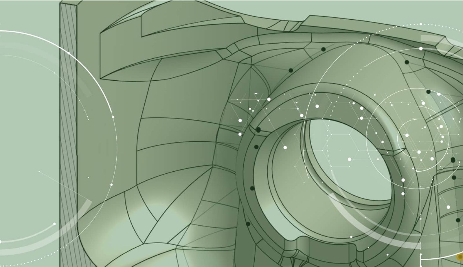
The default orientation is how the model will be shown when it is first opened – in a default isometric view. Looking at the image of the view cube and default planes below, you can see that in its default orientation, front faces front and to the left, right faces right, and top faces top. Clever, eh?
The default orientation of the view cube and default planes.
Most of the time, working to these built-in view orientations makes complete sense. So when you want to view the top of the model, you press Top on the view cube. But there are exceptions, most of which arise from using imported geometry.
The exact same assembly in different default orientations.
Consider the caster models in the image above. Both models are identical except for their orientation. Regardless of whether it was imported, or modeled in Onshape, the model orientation on the right is more realistic and makes more sense. The top of the model is in the Top orientation. This makes it clear to the consumer of this model that this is the orientation in which the model will be used. When assembling, the caster will be inserted the right way up making the assembly process much easier.
There are other considerations, too. Take for example, manufacturing (milling, molding, casting, 3D printing, etc.). In all of these processes, the Z axis points up. The mounting plate from a monitor stand in the image below could be considered as being “Front,” but for manufacturing purposes, the orientation shown is “Top.”
Which way is up?
P.S. All is not lost, however, if you do import or model a part in the “wrong” orientation. When importing parts from other CAD systems into Onshape (most notably those that have the Y axis as up – such as SOLIDWORKS® and Autodesk Inventor®) you can set the imported models in “Y Axis Up” coordinates. Once imported, you can also flip the orientation of the model by editing the Import feature and checking the option “Source is Y Axis Up.”
All manufacturing software and 3D printing pre-processing software enable you to reorient your part so that it is in Z-up orientation, but getting it right in the CAD software makes the whole process run much more smoothly.
2. Symmetry
Most products have at least one plane of symmetry. While it may feel more natural to model the entire shape as you go, so you can easily review your progress, identifying and taking advantage of symmetry can save you an incredible amount of time when modeling.
Thinking about symmetry ahead of time gives you the opportunity to model only a half or a quarter of your design. Thinking about symmetry will also help you determine where your part should be positioned relative to the origin and the default planes. For most symmetric models, it is desirable that the origin is centered and the default planes are used for mirroring.
However, when you’re creating your layout sketches, you naturally want to sketch and dimension full size to control and define the specifications of your product. You can still do this, but build your model using only half of your sketch to create one side or one quadrant. You can add multiple mirror features at the end of your feature list to see how your design is looking, then “rollback” your model before the mirror features to continue adding detail. As more detail is added, you can roll your feature list forward and backwards at any time to see how your design is progressing.
A complex design can be broken down into simple steps by using symmetry.
A good exercise is to consider the milk crate above. While most people will recognize that each side face is identical, it’s easy to miss the fact that only half of a face needs to be modeled and can be mirrored using the angled face in the corner. If only some of the features are symmetrical, model all the symmetry first, then add any other details at the end, like the base of the crate in this example.
3. Patterns
A pattern is a repeating set of features like the ribs in the milk crate example. Identifying patterns of features early in the design and detailing of your product will save you a tremendous amount of time. One of the main benefits of using patterns, other than for speed and convenience, is when it comes to making edits to your design. A change to the original feature propagates through all the pattern features automatically, so large wholesale design changes can be completed in minutes.
Using patterns of features across multiple parts
4. Complexity
One of the main benefits of 3D modeling is being able to add 100% of the detail required for manufacturing. For every part you design, you should always aim to add every fillet, chamfer, and draft feature to accurately portray the finished model. In doing so, you will have more accurate material properties such as mass, volume, center of gravity, etc., more accurate and complete drawings, and your manufacturing friends will thank you for saving them from having to add those details afterwards.
There is one caveat, however. Standard parts such as nuts, bolts, bearings, motors, etc., should not be modeled to the last finite detail. Why? Because you are adding a level of complexity to your assemblies and drawings that has no benefit whatsoever. This complexity can have a detrimental effect on your CAD system’s performance as more graphics power is required to render them.
Adding too much detail can have a detrimental effect on performance.
Consider the two sets of bolts shown above. The bolts on the left look very lifelike. The bolts on the right have been simplified, but have more than enough geometry to accurately represent the parts. To render the helix created by the threads and the text on the head of the bolt, the graphics card needs to render over 150x more triangles in real-time compared to the bolts on the right. Now imagine if you have an assembly with hundreds of nuts, bolts, and holes with threads. Your graphics card is going to go into meltdown!
If you download models from your supplier’s website and they contain too much detail, consider asking them for a simplified version (or simplify it yourself using Onshape’s Direct Editing tools). The only exception to this rule is if you need to 3D print parts with threads.
Next time you start a new CAD project, take the time to consider these four simple techniques for planning your models in advance. Doing so will yield great rewards. Your models will be easier to understand, easier to assemble, and easier to edit in a manner that delivers more predictable results.
Latest Content
- Blog
- Evaluating Onshape
- PCB Studio
- Integrations
- Collaboration
- Consumer Products
- Electronics
- Medical Tech
- Robotics
How Onshape and Altium Are Erasing the ECAD-MCAD Divide
04.30.2026 learn more- Blog
- News from Onshape @ PTC
- PCB Studio
- Integrations
- Consumer Products
- Electronics
- Medical Tech
Introducing the Onshape Altium Connector: True Cloud-to-Cloud ECAD-MCAD Collaboration
04.29.2026 learn more