
02:22
In this Tech Tip you will learn two things:
1. How to create a board in PCB Studio from Onshape Part Studios, and
2. How to add “keep-in” and “keep-out” areas in Onshape to provide the ECAD designer with additional information.
How to Create a Board
The first key benefit of PCB Studio is being able to generate board geometry natively from Onshape in relation to the mechanical assembly.
Here are the steps to create a board in PCB Studio:
- Define the sketch for your printed circuit board.
- Use in-context tools to better drive mechanical constraints for your design.
- Create a solid extrusion with the right thickness for your board (e.g., 1.5mm).
- Rename the part you just created “board” or “PCB”, which will allow PCB Studio to identify this geometry correctly.
- Rename your Part Studio to the name of the board. In this example, we will name it HANDSET_PCB.
- Create a new (or use an existing) PCB Studio tab.
- Finally, sync the Part Studio you created into PCB Studio.
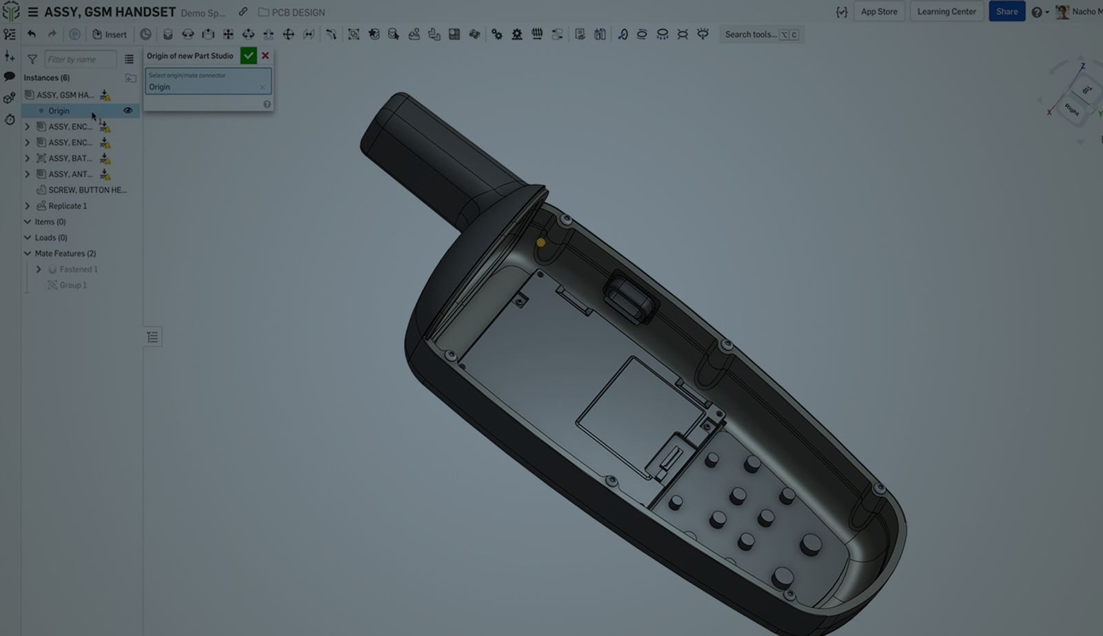
Part Studio:
Using in-context references in a Part Studio makes it easy to reference the assembly, you can use the assembly context as a guide to create your PCB. This means faster and more accurate workflows as you design within the constraints in your mechanical assembly.
PCB Studio:
After following these steps you will have a blank board in PCB Studio that you can export as IDF format. You can push any new changes or edits to your board into PCB Studio by simply syncing the board again.
Creating Keep-Out & Keep-In Areas in PCB Studio
In the context of the mechanical assembly, you can build keep-out and keep-in areas that can be downloaded with your IDF file for reference in the ECAD tool. Plus, they can be set up in a few steps:
- Constrain your board into your assembly
- Hide any components that don’t need to be referenced in the keep-out, keep-in areas
- Edit your board in the context of the assembly
- In the Part Studio, create construction parts that represent your keep-out regions. These parts should be named “PLACE_KEEPOUT”
- In the Part Studio, create construction parts that represent your keep-in regions. These parts should be named “PLACE_KEEPIN”
- In your PCB Studio tab, sync from the Part Studio
You should now be able to see your keep-in, keep-out areas represented in the PCB Studio properly.
Part Studio:
In-context design will once again prove extremely useful when defining the keep-out and keep-in areas. By creating a context around the mechanical assembly, the collaborative workflows with ECAD will be more efficient, as you create direct references.
PCB Studio:
With the final geometry defined in PCB studio, download your IDF and start detailing your PCB!
To learn more about making a Board and setting up the keep-out and keep-in areas follow along with the video:
New to PCB Studio? Check out our PCB Studio Fundamentals self-paced course in the Onshape Learning Center.
Friends Don’t Let Friends Use Old CAD!
Know a colleague who could benefit from our cloud-native, fully-featured collaborative design platform?
Latest Content
- Blog
- Becoming an Expert
- Assemblies
Built to Scale: Why Large Assemblies Don’t Slow Down in Onshape
07.16.2026 learn more- Blog
- News from Onshape @ PTC
- Artificial Intelligence
Onshape Labs: AI in CAD Guided by Designers, Driven by Innovation
07.15.2026 learn more- Blog
- Evaluating Onshape
- Data Management
- Collaboration
- Artificial Intelligence
How the Most Underrated CAD Feature Improves Design Workflows
07.09.2026 learn more