
1:22
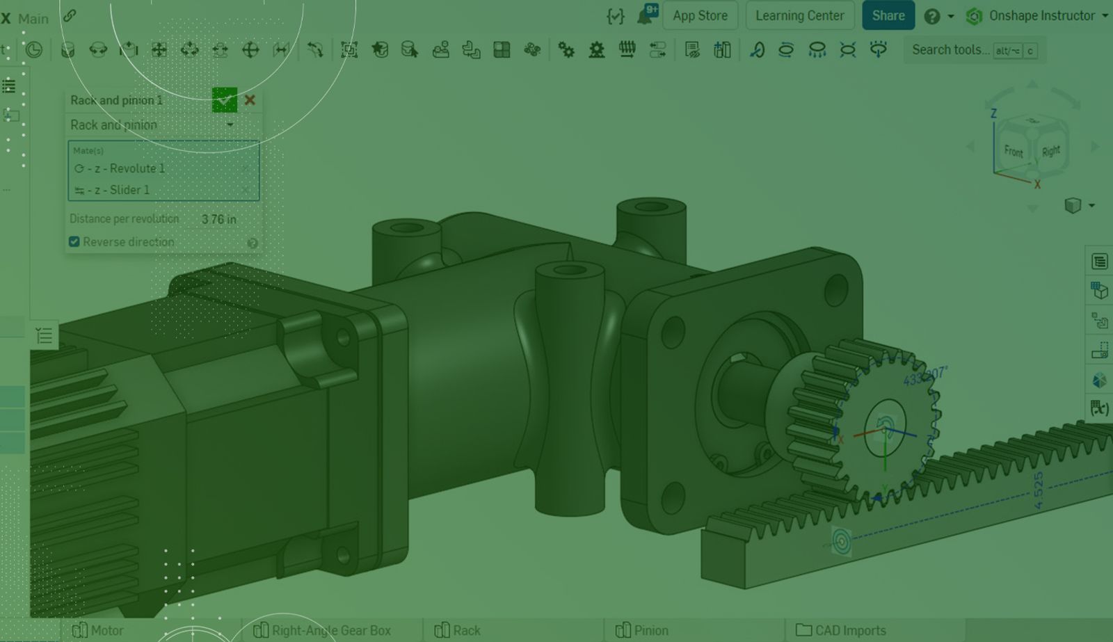
In mechanical design, rotational and linear movement between components are often required. In the assembly below, a motor attached to a gearbox drives a rack and pinion setup.
A Rack and Pinion Relation feature easily captures the movement between the rack (straight track) and pinion (gear).
Using the Rack and Pinion Mate Relation in an Assembly
The Assembly already contains a Revolute Mate between the gearbox and pinion and a Slider Mate between the origin and rack.
Model the movement between these two components using the Rack and Pinion Relation feature. This relates a Mate with rotational degrees of freedom to a Mate with a linear degree of freedom.
Click the Rack and Pinion Relation feature on the toolbar, then select the Revolute and Slider Mates, either in the graphics area or from the Mate Features list. These two Mates provide the exact degree of freedom required for the relation.
Input distance per revolution. This value defines the amount of linear travel. For each revolution of the pinion, the rack moves linearly by this amount.
To move the rack and pinion opposite each other, check the Reverse Direction box.
With all parameters set, click the checkmark to close the dialog and accept the new relation.
With the relation created, moving one object updates the position of the other.
Watch the video below to get more details on the subject of Rack and Pinion Relations.
Check out the Onshape Help Documentation, where you will find more information on using Rack and Pinion, Gear, Screw, and Linear Relation features. Also, be sure to review the Advanced Onshape Assemblies class in the Onshape Learning Center.
The Onshape Learning Center
Take self-paced courses, read articles, or sign up for an instructor-led training session.
Latest Content
- Blog
- Becoming an Expert
- Assemblies
Built to Scale: Why Large Assemblies Don’t Slow Down in Onshape
07.16.2026 learn more- Blog
- News from Onshape @ PTC
- Artificial Intelligence
Onshape Labs: AI in CAD Guided by Designers, Driven by Innovation
07.15.2026 learn more- Blog
- Evaluating Onshape
- Data Management
- Collaboration
- Artificial Intelligence
How the Most Underrated CAD Feature Improves Design Workflows
07.09.2026 learn more