
1:11
Some assembly designs require the motion of one mate to actuate the motion of another mate.
This behavior can be easily captured using Mate Relations. With Mate Relations, you can create a relationship between two different degrees of freedom.
Example: Using the Screw Mate Relation
In this example, a relationship will be created between the two degrees of freedom in a single cylindrical mate. Recall that cylindrical mates allow rotational motion about the axis of a cylinder and linear travel along the axis. Using a Screw Relation, we can model the motion of a screw.
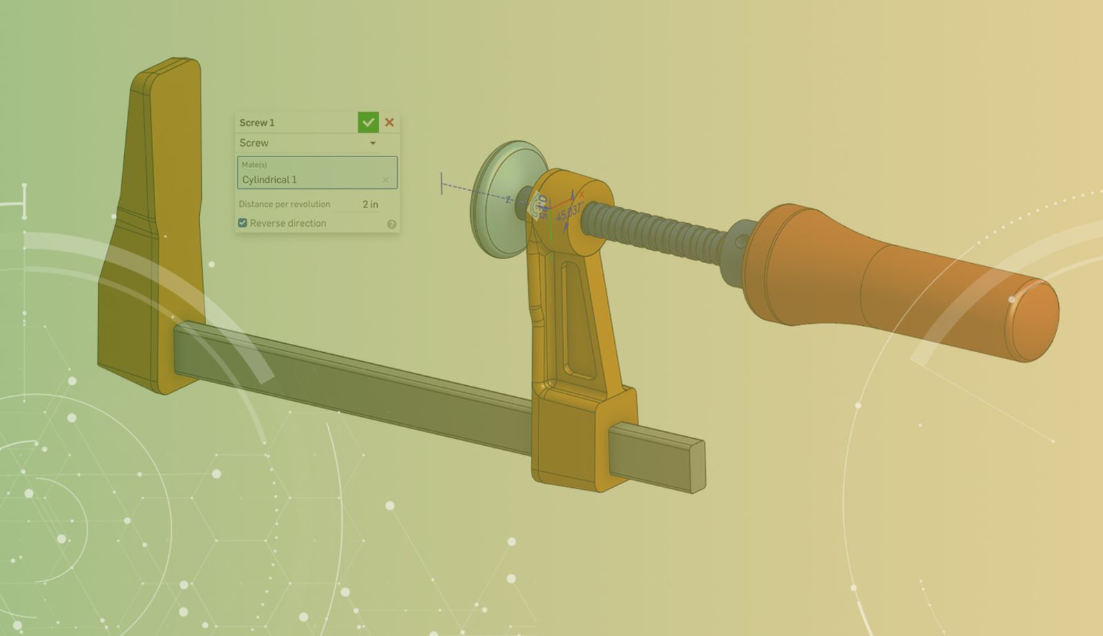
In the image below, the rotation of the red handle causes the blue shaft to move along its axis, just like a screw.
Mate Relations Are Easy to Create
Again, using the Screw Relation as an example, you can see that using this tool couldn’t be easier. Select the cylindrical mate, then click the Screw Relation tool in the assembly toolbar. Enter the required distance per revolution, and you’re done!
This Tech Tip helped you learn how to create a Screw Mate Relation. Get more details on this subject by watching the video below.
For more information on Mate Relations, check out the Onshape Help Documentation. Here you’ll also find information on how to use the other types of mate relations: Gear, Rack and Pinion, and Linear.
Or take the Advanced Onshape Assemblies class in the Onshape Learning Center.
Latest Content
- Blog
- Becoming an Expert
- Assemblies
Built to Scale: Why Large Assemblies Don’t Slow Down in Onshape
07.16.2026 learn more- Blog
- News from Onshape @ PTC
- Artificial Intelligence
Onshape Labs: AI in CAD Guided by Designers, Driven by Innovation
07.15.2026 learn more- Blog
- Evaluating Onshape
- Data Management
- Collaboration
- Artificial Intelligence
How the Most Underrated CAD Feature Improves Design Workflows
07.09.2026 learn more