
 Create a Student Account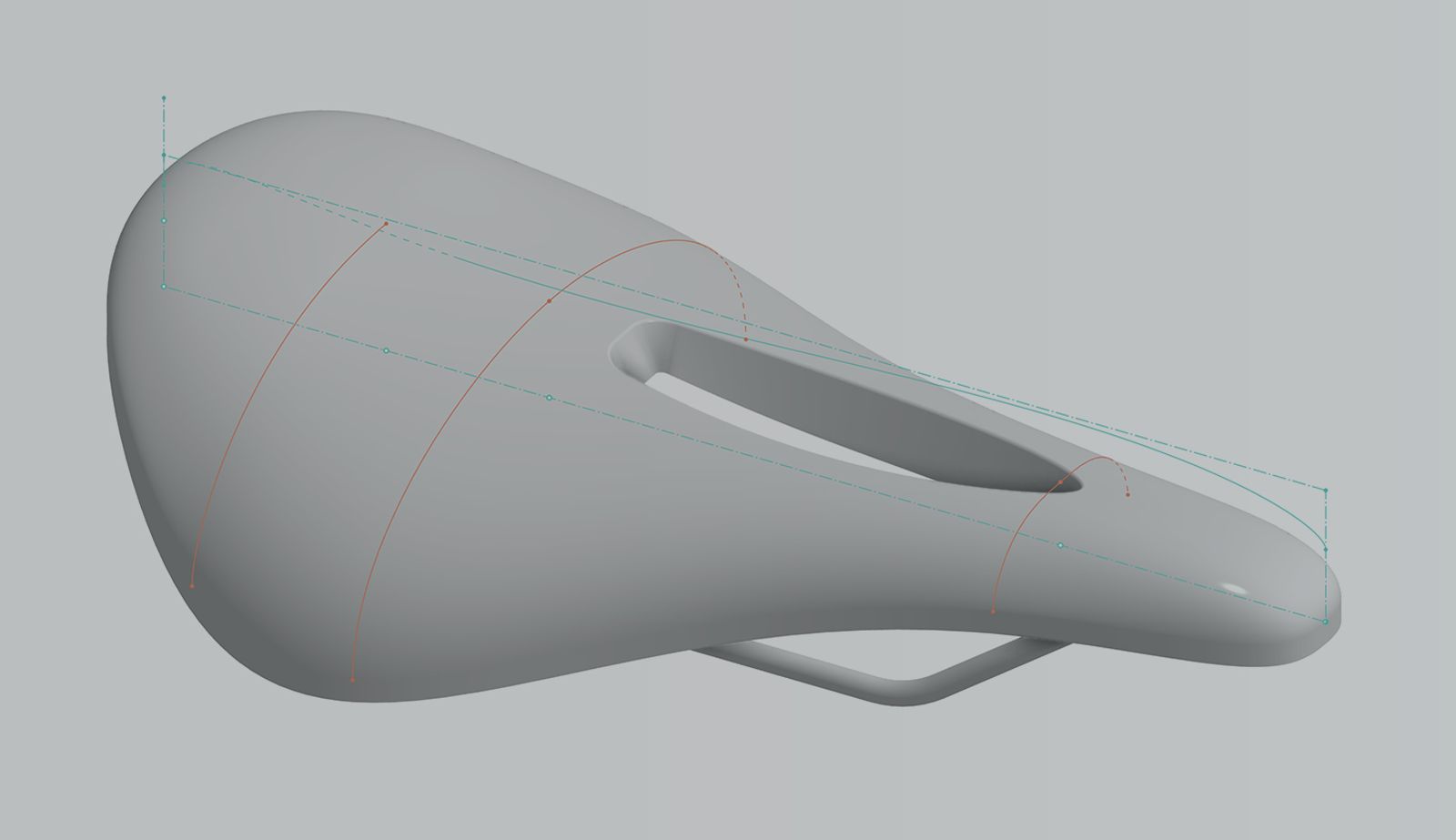
00:00
Summary
Creating geometries in CAD software often requires defining a construction plane relative to existing geometry, such as a plane, edge, axis, point, or surface. Onshape’s Plane tool provides a wide range of options for creating reference planes. The key is understanding which types of geometry can be used as inputs and when to use each method.
In this Tech Tip, we’ll take a closer look at the available plane types in Onshape, the geometry they can reference directly, and a few custom features that can extend those capabilities even further. By the end, you’ll have a better understanding of how to quickly create a construction plane for each modeling scenario.
Plane Parallel to Planar Geometry
To create a plane parallel to existing planar geometry, use Offset or Plane point. In addition to planes and planar faces, the Offset option can also reference closed sketch regions, circular edges, and conical edges, reducing the need to create intermediate reference geometries.
Plane Normal to a Line or Curve
The Point normal option creates a plane perpendicular to a line or an axis. You can directly select cylindrical or conical faces, which already contain axis information.
The Curve point option allows you to create a normal plane at any location along a curve. Combined with the CT Points custom feature, you can position the plane precisely anywhere along an edge or a curve.
Uniformly-Spaced Construction Planes
Evenly spaced sketch planes are frequently used in surfacing workflows such as Loft or Boundary surface.
For constant spacing, create a single plane or Mate connector, then replicate it using a Linear pattern.
When the planes must be distributed evenly between fixed start and end points, create a reference line, and a plane at the start of the line, then use the Curve pattern tool with the Equal spacing option.
Several custom features, such as Multi-plane and Intermediate Planes, can generate an entire set of evenly spaced planes in a single step, reducing the feature count.
Unevenly-Spaced Planes
When you need to position the planes at specific locations, a common workflow is to create a sketch containing a line and dimensioned points, which can then drive Plane point, Point normal, or Curve point planes. When design changes happen, you can make the position adjustments within the same sketch.
Plane Coincides with a Line
Use the Line angle option to create a plane that rotates about an edge or axis. Select the cylindrical and conical faces directly as the rotational axis, then continue to select the second entity to control the plane’s starting orientation.
Additional reference curves can be generated using tools such as Isoparametric Curve, Isocline Curve, or Euclidean Offset Curve, providing more options for alignment and orientation.
Mid Plane and Three Points
The Mid plane option creates a plane centered between two planes so that the distance or angles are equally distributed. If you select a curve or a line, it places a normal plane at the midpoint.
The Three points option creates a plane through any three points and is the fundamental definition of a 3D plane.
Tangent to a Cylindrical Face
The Tangent option creates a plane that remains tangent to a cylindrical face. You can orient the plane to be parallel to another plane or to pass through a point on the face.
If you preselect the entities, the Plane tool often automatically switches to the most appropriate option (this is true for other options as well).
Tangent to a Complex Curved Face
Creating tangent planes on complex geometry requires additional tools.
The Surface Tangent Plane and 3D Points FS custom features allow you to define both the point of tangency and the surface normal within a single feature using the built-in UV parameter controls.
Point Tool
Points are commonly used as anchors for construction planes and as references for defining the start or end conditions of features.
The CT Points custom feature allows you to create points using XYZ coordinates, positions along a curve, or locations directly on a face. These points can then be used as inputs for planes, mate connectors, and other features.
Axis Tools
In most Onshape workflows, creating axes is not necessary because cylindrical and conical faces inherently define an axis. However, there are situations where a visible axis could improve clarity on the design intent.
Several custom features, such as Default Axes, FeatureScript Axis, and Reference Axis, can generate axes for visual cues and feature creation.
This Tech Tip helped you explore Onshape’s Plane tool and how you can easily create construction planes, axes, and points with the help of custom features in different scenarios.
Watch the video below for more:
For more on this topic, explore the Onshape Learning Center’s training materials and videos about using Plane tools, such as the Reference Planes course.
Friends Don’t Let Friends Use Old CAD!
Know a colleague who could benefit from our cloud-native, fully-featured collaborative design platform?
Latest Content
- Blog
- Becoming an Expert
- Assemblies
Built to Scale: Why Large Assemblies Don’t Slow Down in Onshape
07.16.2026 learn more- Blog
- News from Onshape @ PTC
- Artificial Intelligence
Onshape Labs: AI in CAD Guided by Designers, Driven by Innovation
07.15.2026 learn more- Blog
- Evaluating Onshape
- Data Management
- Collaboration
- Artificial Intelligence
How the Most Underrated CAD Feature Improves Design Workflows
07.09.2026 learn more