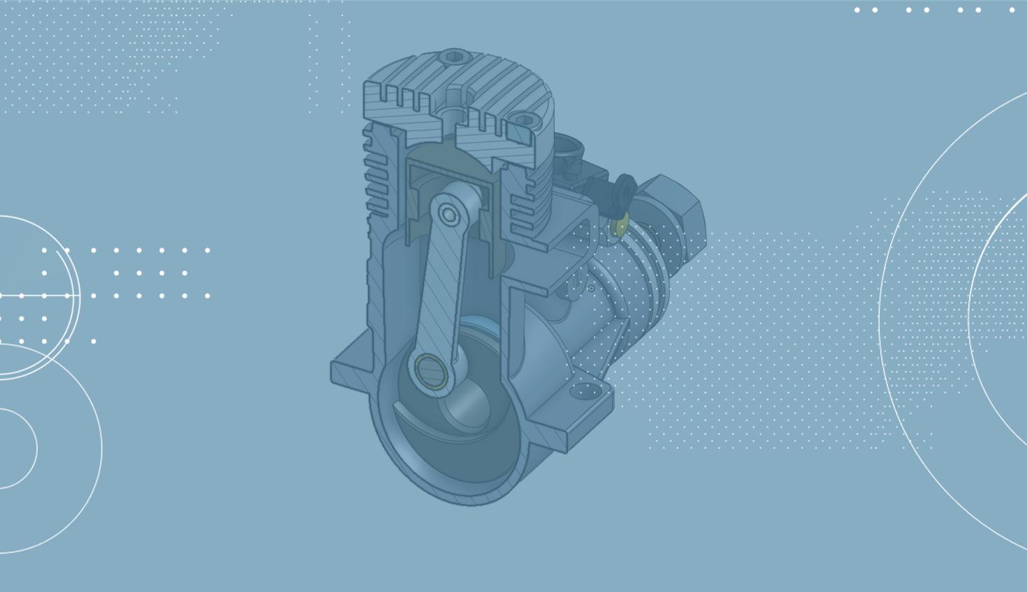
1:34
Creating 3D geometry often starts with 2D sketches, which serve as the basis for the entire design. To define important main dimensions of a design, a master sketch or several sketches are used in Part Studios. These sketches serve as the base geometry for the rest of the design. The Part Studio allows users to create several parts in one place. This is especially helpful when geometric dependencies exist between parts.
It becomes more complex when the designed parts have movement and these movements determine the design as well as dimensions for parts.
To animate this movement using only 2D sketches, the individual sketch elements created in a Part Studio can be inserted into assemblies and brought together using Mate Connectors.
This is an easy and quick way to check the basic dimensions of a design using moving 2D sketches without having to create many static 2D sketches in Part Studios.
First, create sketches in a Part Studio for the elements that you want to model later.
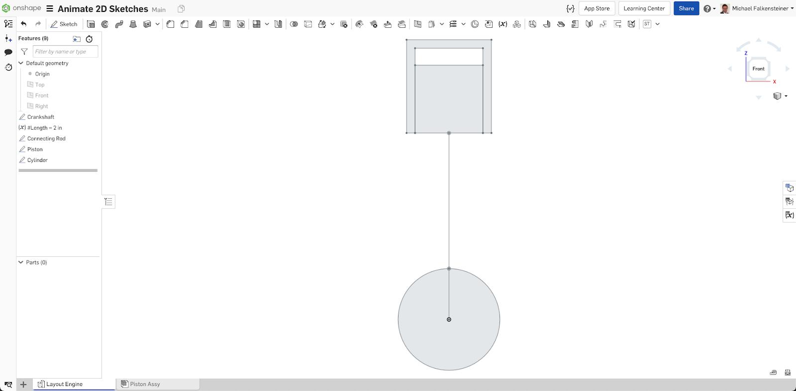
These sketches can be inserted in an assembly the same way as parts or assemblies.
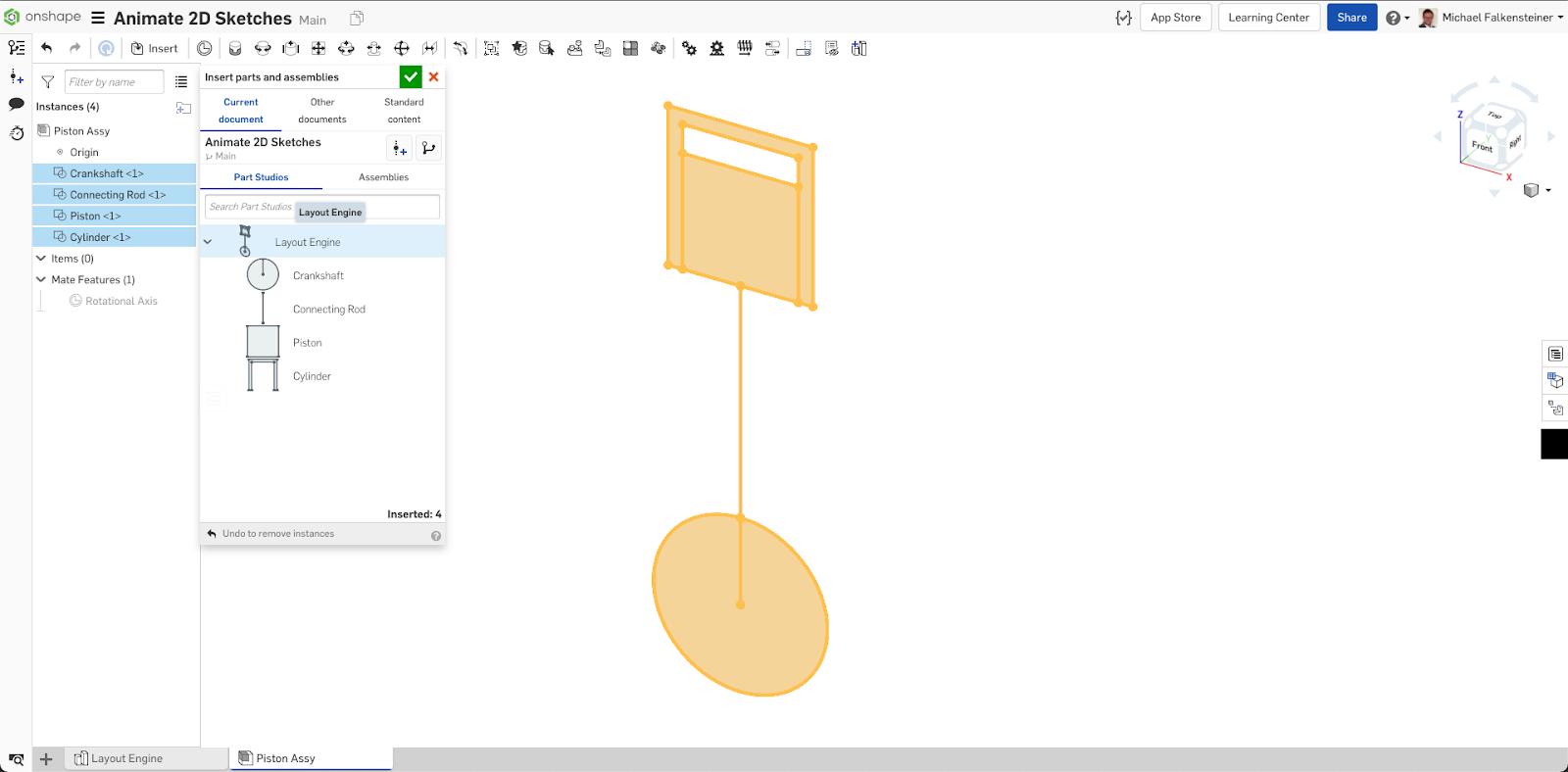
The individual sketch elements can now be brought together by using Mate Connectors. To learn more about mates, visit the Onshape Learning Center course “Mating Basics: An Introduction to Onshape Mating Strategies”.
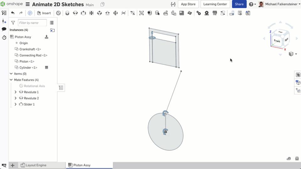
With this system, the sketches are not only animated, but also position values can be specified and displayed.
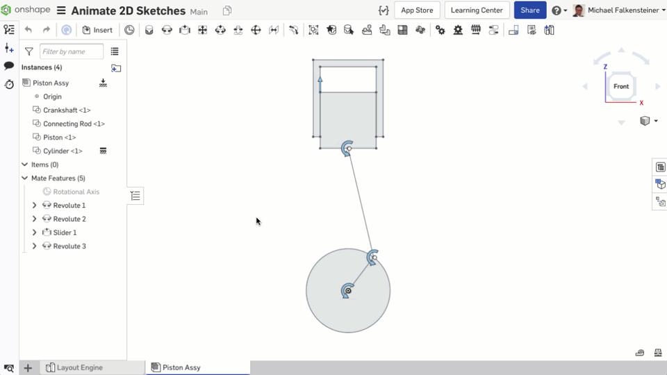
This is just a simple example of how 2D sketches can be used to quickly and easily animate movements in assemblies to get basic dimensions for your design.
Learn more about this process by watching the video below:
Want to learn more about Sketching? Check out the video, “Onshape Sketching Tips for Power Users”.
Interested in learning more Onshape Tech Tips? You can review the most recent technical blogs here.
Latest Content
- Blog
- Becoming an Expert
- Features
- Data Management
How Onshape's Repair Tool Fixes Broken References
01.29.2026 learn more
- Blog
- Startup
How Hardware Startups Can Cut Costs, Find Funding, and Scale in 2026
01.28.2026 learn more
- Blog
- Customers & Case Studies
Future Joinery Systems: Bridging the Gap Between Architecture and Manufacturing with PTC’s Onshape
01.23.2026 learn more


