
1:50
Mesh models are 3D models represented by a series of triangles attached to each other. Many meshes can have anywhere from thousands to millions of triangles. Frequently, these models come from 3D capture to scan a part for reverse engineering. When captured data is imported into a CAD program like Onshape, the geometry frequently appears offset from the origin and rotated with respect to the primary planes.
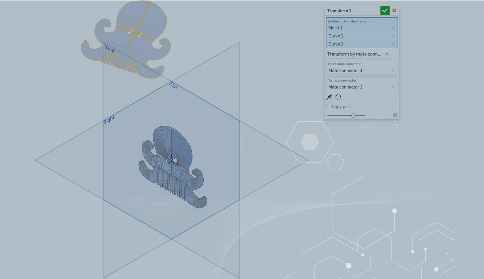
One common way to orient a model is to transform it from one Onshape Mate connector to another. Since it is a mesh, the implicit Mate connector points will only wake up on the mesh points between elements which usually aren’t sufficient. A good way to work around this is using 3D fit splines. Let’s go through the steps.
First, start a new 3D fit spline and select two mesh points. The center of the resulting line is where you desire the origin to be. In this case, the points create a line that runs across a planar face, but the line can also pass through the mesh. The start and end magnitude are unimportant because the result is a line.
If needed, add at least one additional 3D fit spline that will help to orient the primary or secondary axis of the Mate connector.
Define a Mate connector at the center of one of the 3D fit splines and use the other splines to position the primary and secondary axes correctly. Select the mesh as the Owner part.
Create another Mate connector at the origin. Select the mesh as the Owner part again.
Finally, move the mesh using Transform. Select the 3D fit splines as well so they will move with the mesh model. Select the option to Transform by Mate connector and move from the first connector to the second. The Flip primary axis only flips the Z axis. If the X or Y axes need adjustment, go back to the original Mate connector to change the direction.
The result is a mesh model that is correctly centered on the origin and oriented correctly with respect to the primary planes.
Interested in learning more Onshape Tech Tips? You can review the most recent technical blogs here.
Latest Content
- Blog
- Evaluating Onshape
- Electronics
- Integrations
- PCB Studio
How Onshape PCB Studio Pulls 3D Component Models Straight from Altium 365
05.21.2026 learn more- Blog
- Evaluating Onshape
- Collaboration
- Data Management
What’s the Difference Between File-Based and Cloud CAD?
05.20.2026 learn more- Blog
- Customers & Case Studies
- Arena PLM Connection
The Cloud-Native Workflow Behind Coco’s Next-Gen Delivery Robot
05.14.2026 learn more