
1:27
Today’s Tech Tip will focus on using offsets when using the Extrude feature. Onshape features are designed to consolidate many different functions all within the same tool. Offsets are used either to offset from the face/sketch region to extrude, or as part of the end condition.
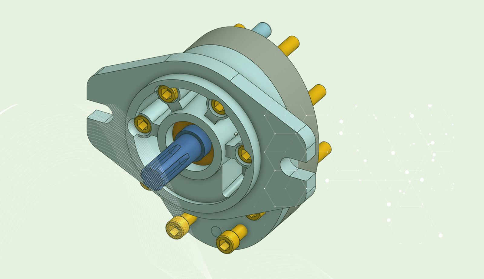
In the hydraulic steering pump model below, there is a master sketch to define the bolt circle. The boss needs to be offset from the original sketch, while the hole will be extruded directly from the sketch. Without the ability to offset, you would need to separate them into two different sketches.
Begin an Extrude, select an end condition, and the regions to extrude. If you choose “Blind,” enter the overall depth (including the offset). The feature will show it extruding from the source sketch. To offset it, select the option for a second direction. Make sure it is pointing in the same direction as the first, and set the depth to what you would like the offset to be.
Now, the boss needs a hole added for the bolt. The hole will start at the sketch, but will be a specific offset from the bottom. Select the regions to extrude and choose the end condition “Up to face.” This enables an input for “Offset distance.” Next, choose the face to offset from and put in a distance.
The offset input is available for up to next, face, part and vertex end conditions.
Now you can use offsets in the start and end conditions for an extrude feature. This will reduce the number of features and sketches you will need to complete new parts.
Interested in learning more Onshape Tech Tips? You can review the most recent technical blogs here.
Latest Content
- Blog
- Evaluating Onshape
- Arena PLM Connection
The Cloud-Native CAD-PDM-PLM Workflow That Finds Problems Before They Cost You
06.11.2026 learn more- Blog
- News from Onshape @ PTC
- Artificial Intelligence
- Robotics
How Multi-Agent Orchestration Between Onshape and NVIDIA Improves CAD-to-Simulation Workflows
06.01.2026 learn more- Blog
- Evaluating Onshape
- Robotics
- Aviation, Aerospace & Defense
- Collaboration
- Integrations
- Arena PLM Connection
- Data Management
Why the Best Hardware Teams Have Started Talking Like Software Engineers
05.28.2026 learn more