1:43
Whether you are working on a drawing or in an assembly, there will ultimately come a time when you need to reference more than just the part you designed. Inserting and using sketches or surfaces can be very useful for actions such as part alignment off of a master sketch or dimension references in a drawing. Let’s take a look at how to insert sketches and surfaces for both Onshape drawings and assemblies.
Inserting Sketches and Surfaces in an Onshape Assembly
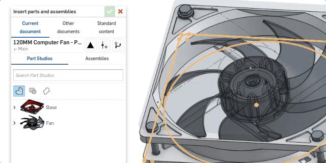
From within an Onshape assembly tab, click on the insert button to open up the insert dialog. From here, navigate to the desired Document and select the Part Studio or assembly that contains the sketches and surfaces you would like to insert. Keep in mind that you can click on the words ‘Part Studios’ and ‘Assemblies’ to toggle between them in the dialog.
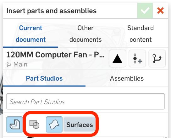
Below the navigation and search of the insert dialog, you will notice a few icons, one of them may already be highlighted in blue. Note that you will only see the icons of the components that exist in the Document you are inserting from. From here, you can toggle to reveal the sketches and surfaces that exist within the Part Studio or assembly to select for insertion. Don’t forget to hit the green check box to finalize inserting your components.
Inserting Sketches and Surfaces in an Onshape Drawing
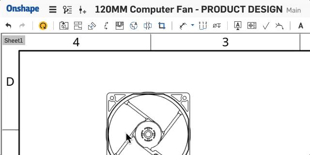
Inserting sketches and surfaces into a drawing is very similar to the steps for inserting into an assembly. First, select the option to insert a view and you will see the same filter icons to toggle, revealing the sketches and surfaces to insert. Notice that you can choose your view direction for surfaces, but must insert a sketch normal to its plane.
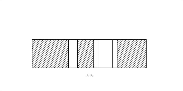
You can also hide/show sketches for section views, broken-out section views, and crop views within a drawing by right-clicking on that view and choosing the sketch to insert.
Interested in learning more Onshape Tech Tips? You can review the most recent technical blogs here.
Latest Content
- Blog
- Becoming an Expert
- Assemblies
- Simulation
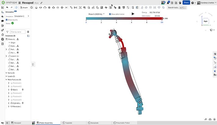
Mastering Kinematics: A Deeper Dive into Onshape Assemblies, Mates, and Simulation
12.11.2025 learn more
- Blog
- Evaluating Onshape
- Learning Center
AI in CAD: How Onshape Makes Intelligence Part of Your Daily Workflow
12.10.2025 learn more
- Blog
- Evaluating Onshape
- Assemblies
- Drawings
- Features
- Parts
- Sketches
- Branching & Merging
- Release Management
- Documents
- Collaboration
Onshape Explained: 17 Features That Define Cloud-Native CAD
12.05.2025 learn more


