2:02
After many hours of hard work designing a product, it’s now time to make sure everyone knows who made it. Here are the steps you can take to bring a DXF/DWG of your logo into Onshape and use it to emboss or cut into your designs:
Insert
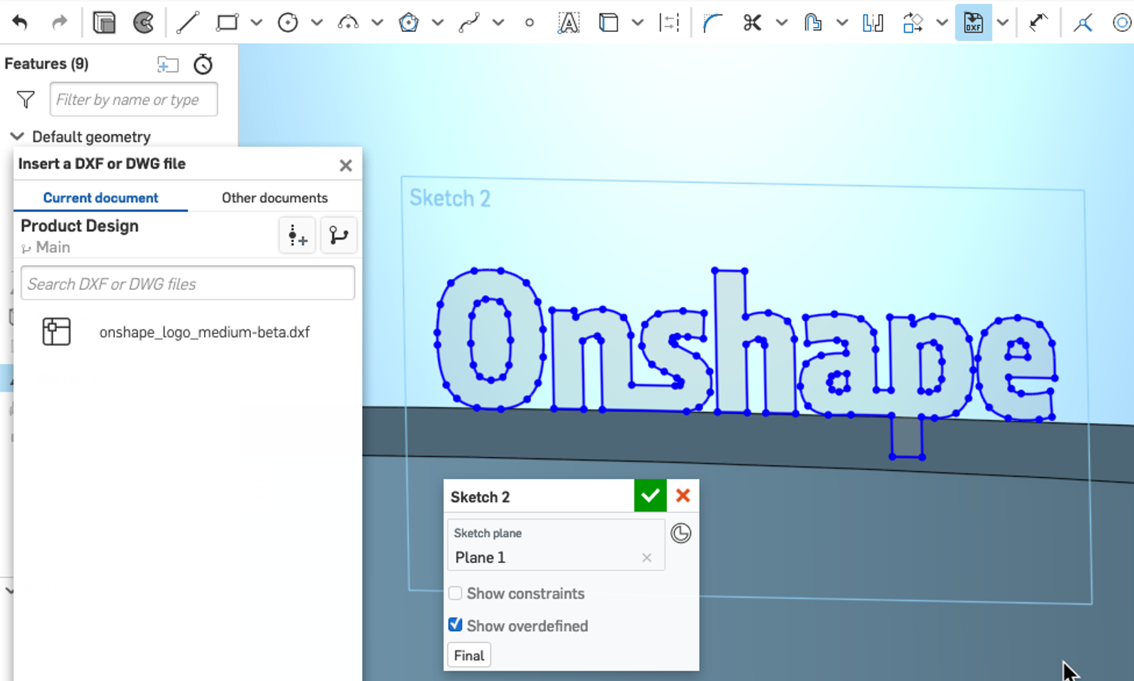
After importing your company logo in as a DXF or DWG file into an Onshape Document, you can then create a sketch and insert the file into that sketch plane. If you are embossing a planar surface, then a sketch can be made on that face. There are various options within the insert dialog to modify the units and choose where it is positioned. If this is a common operation, then consider making a logo template to reference from a standalone Document.
Scale
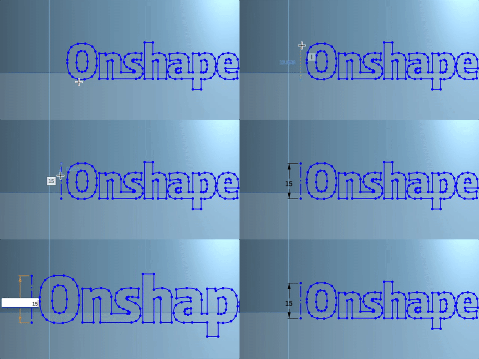
The resulting sketch entities that appear after inserting a DXF/DWG may not be the correct scale. Within Onshape, setting the first dimension in a sketch will cause all sketch entities to scale proportionally to that dimension. Create a construction line that is horizontal to the upper and lower bounds of the logo’s height and then dimension that construction line to the maximum desired height.
Wrap
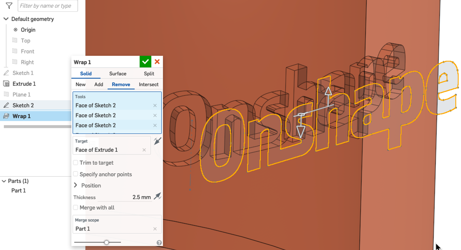
For cylindrical components, the last step is to perform a wrap operation. The sketch entities can be placed wherever is required as well as the end-type operation to extrude or remove material from the component.
Transform
If the wrap feature is not being utilized, moving the logo into position will have to be accomplished from the sketch level with the sketch transform tool. Highlight the sketch entities to transform, then right-click and select “transform sketch entities” from the context menu. A triad manipulator will become available to move the sketch entities around and snap them to relevant points. Left-click to complete the transformation.
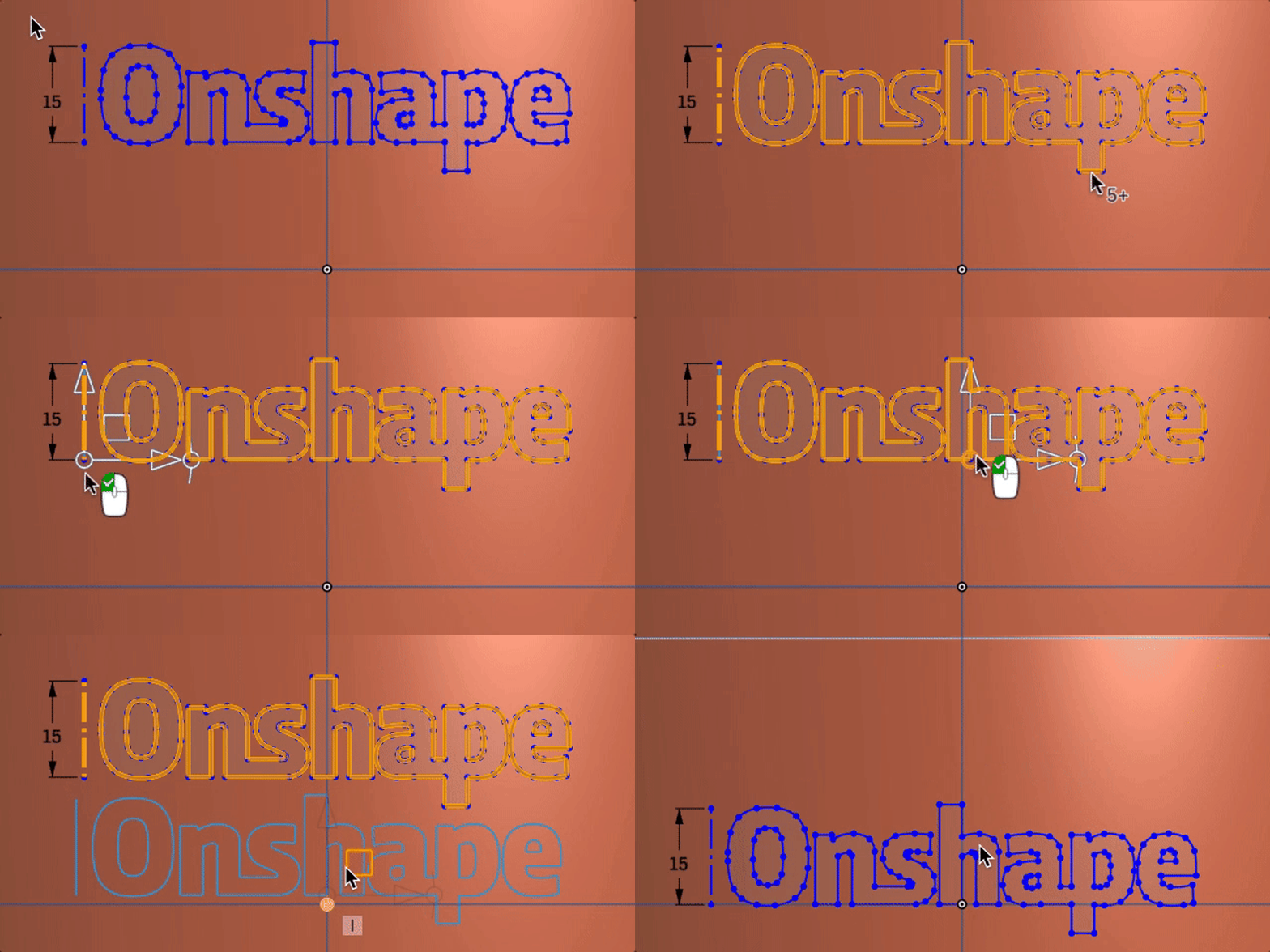
Note: Inserting DXF/DWG entities into a sketch leaves the entities with no constraints between them. It may be necessary to apply the “fix” constraint to the entities to keep them from moving during parametric changes.
Emboss
The last step is to use this logo profile to emboss it onto a part. This can be accomplished by several methods depending on the desired outcome of the logo. The simplest solution is to use an Extrude Cut or Add operation of the logo sketch profile onto a piece of geometry.
Interested in learning more Onshape Tech Tips? You can review the most recent technical blogs here.
Latest Content
- Blog
- Becoming an Expert
- Sheet Metal
Two Views, One Model: Faster Sheet Metal Design in Onshape
02.12.2026 learn more
- Blog
- Customers & Case Studies
- Collaboration
- Consumer Products
RigStrips Boosts Design Speed Using Onshape's Collaborative Tools
02.11.2026 learn more
- Blog
- Becoming an Expert
- Features
- Data Management
How Onshape's Repair Tool Fixes Broken References
01.29.2026 learn more


