
2:56
Today's Tech Tip focuses on blending and repairing fillets using Onshape’s Fill Surface feature.
One of the most widely used features in any CAD system is a fillet. Fillets are used to break sharp edges, add structural integrity, or to simply add style to a design. Fillets have the ability to propagate along tangent connected edges making it easy to fillet several edges at the same time. However, In some situations, fillets that overlap or converge several edges into one can cause undesired results or poor blends between edges.
Let’s take a look at how to repair these fillets using surfacing techniques.
In this example, these three edges need to be filleted.
Edges to fillet.
After the fillets are added, we can see that the fillets form a poor transition where the three edges meet.
Three filleted edges converging.
In order to blend these fillets, a series of sketches and split face operations will need to be created. The first sketch is drawn on the top face using the Spline tool. The spline is constrained to the edges of each fillet while also matching tangency. Two additional lines are drawn to split the sides of the fillet.
Sketch 1 on the first face.
Next, the Split Face feature is used to split the face of the fillets and the top face.
Split face using sketch 1.
On the second face, another spline is used matching tangency to each edge and constrained to the edge of the first split face operation.
Sketch 2 on the second face.
The Split Face feature is used again to split the face of the second side.
Split face using Sketch 2.
The third face to split is not planar, so a sketch on this face is not possible. In situations like this, users can create a new plane or use an existing plane to sketch on. In this case, the top plane is used to construct the third and final sketch for the blending operation.
Sketch 3 on Top Plane.
A third Split Face feature is used to split the remaining face. The area to blend has now been isolated and needs to be removed.
After all faces are split.
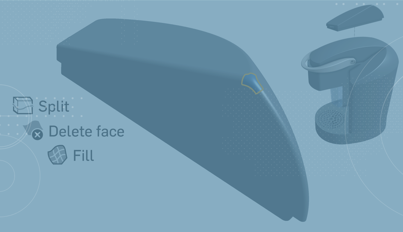
The Delete Face feature, with the option to leave open, will remove these faces and convert the solid part into a surface.
Split faces deleted.
Last, a Fill Surface feature is used to patch the area while matching the appropriate continuity to the surrounding edges. The surface is added to the surrounding surfaces using the Merge With All option. This creates a watertight model and converts the surface back to a solid part.
Fill surface added.
Below we can see the model before and after the blend operation. The Shaded Without Edges option has been turned on to see the area more clearly.
Before blending.
After blending.
This is one of many examples of using surfaces for blending operations. Workflows like these will add more features to your model, but the end results are worth the effort. When details count, surface blends will help you achieve quality end results.
Find out more by watching the video below:
To learn more about the Fill Surface feature, check out the Advanced Part and Surface Design Learning Pathway in the Onshape Learning Center. You can also check out the related Tech Tip on how to use the Sweep feature for blending operations.
Interested in learning more Onshape Tech Tips? You can review the most recent technical blogs here.
Latest Content
- Blog
- Evaluating Onshape
- Electronics
- Integrations
- PCB Studio
How Onshape PCB Studio Pulls 3D Component Models Straight from Altium 365
05.21.2026 learn more- Blog
- Evaluating Onshape
- Collaboration
- Data Management
What’s the Difference Between File-Based and Cloud CAD?
05.20.2026 learn more- Blog
- Customers & Case Studies
- Arena PLM Connection
The Cloud-Native Workflow Behind Coco’s Next-Gen Delivery Robot
05.14.2026 learn more