5:02
Sheet metal design doesn’t get much glory because many of the parts are utilitarian – things that blend in the background like cases, covers, clips, brackets and ductwork. But the more you think about sheet metal, the more you realize how the world wouldn’t run without it.
The Onshape development team has thought a lot about how sheet metal parts get made, and have aimed to eliminate the current frustration often experienced between designers and manufacturers. Why do parts that seem perfect in the CAD model sometimes wind up being duds on the shop floor?
And how does Onshape’s approach differ from the way that traditional CAD systems have tackled sheet metal? We asked Scott Harris, Onshape’s VP of Product Definition and User Experience, to give us the scoop.
Q: Every other professional CAD system already has sheet metal tools. Why are Onshape’s new tools such a big deal?
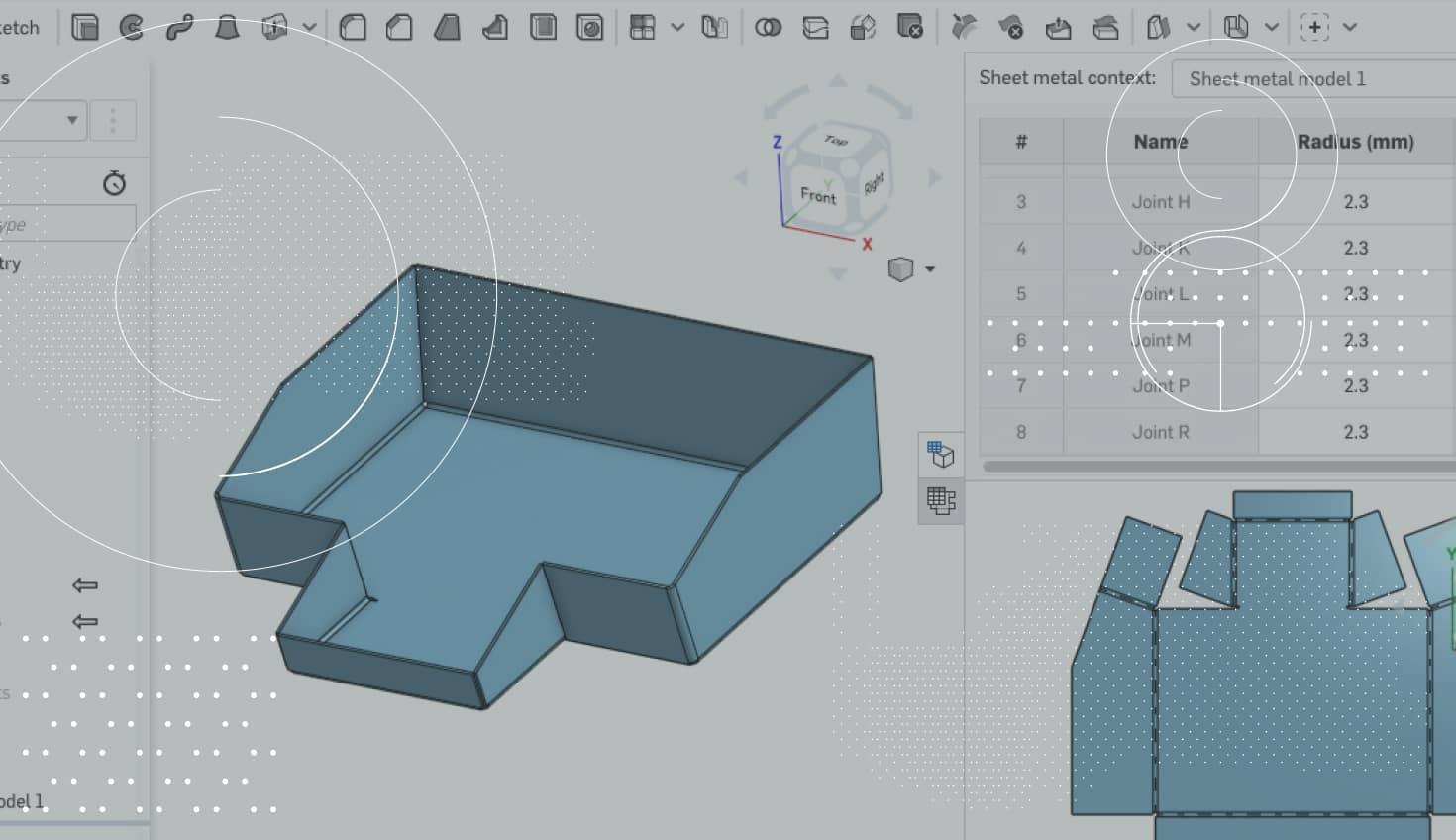
A: This isn’t a case of Onshape catching up with other products. Like everything else with our approach to full-cloud CAD, we’re doing it differently and better. Simultaneous Sheet Metal augments every other cool thing we’ve done. It amplifies our Managed In-Context Editing. You can wrap your assembly with sheet metal and use the assembly components as contributors to the sheet metal shape. It works in a Part Studio, where you can conveniently model multiple sheet metal parts together. Having the flat view simultaneous to the folded view also gives you a lot of advantages.
Q: How so?
A: Because you can monitor how the manufacturing side will see it while you're modeling it. If you pick bends in the wrong place, the system will give you a visual indication immediately that there's something wrong with the flat pattern. By showing the interference and you can very easily correct issues.
With the flat pattern and folded views... think about it like you're standing in front of two funhouse mirrors. In one view, you're tall and skinny – and in the other one view, you're short and fat. But if you look at your nose, your nose maps perfectly into both of them. For example, if I pick an edge in the flat, or a bend in the flat, it shows me that corresponding geometry in the folded view. Or I could pick something in the folded view and it shows me the corresponding geometry in the flat. The system also highlights the corresponding entry in the Bend and Rip Table view. It cross-highlights between all of the relevant views.
Q: What’s the biggest benefit of the table view?
A: The table view is a list of all the bends and rips. It is used to view and manage bend information such as order, radius and angle. Or you can change rips to bends, and bends to rips. And you can select the type of rip style (the way the edges overlap) as well. It's a very convenient way to work by having all these views together.
Scott Harris, Onshape’s Co-founder & VP of Product Definition and UX
Q: How would you describe the state of collaboration between sheet metal designers and sheet metal fabricators right now?
A: We talked with a lot of designers and fabricators and listened to the kinds of things they care about. Sheet metal shops frequently complain about the models that they take in. What happens is that they’ll get a model and they can't manufacture it. Where the bends are, the sizes of the gaps, the configurations of the corners are – sometimes those things are not producible. Even though the design may look great, the manufacturer basically says “This is crap!” and they have to remodel it from scratch.
Q: Why does this happen?
A: It's no one's fault. The designers don't necessarily know what tooling will be used or exactly what gauges will be used. So a lot of the fabrication techniques in sheet metal are dependent on the brake configuration and the size and shape of their tooling and the size and thickness of their stock. Different shops will manufacture even the same thing differently based on their tooling resources.
The point is that it's very rarely the same person who is doing the designing and the manufacturing. Again, if the designer doesn’t know exactly what's sitting in the stockroom and the tool crib of the shop, they can't design it perfectly. That stuff can only be done when they measure up the stock and put in the thickness – when they can determine the K-factors or bend allowances for the types of tooling they're going to use and the size of the bends they're going to use. So it's all done downstream.
Using Onshape’s new sheet metal tools within Part Studios, designers can work on several sheet metal parts at once and see how they fit in an assembly.
Q: So how does Onshape’s Simultaneous Sheet Metal change the equation?
A: We've designed a system that lets manufacturers take the model and re-configure it without remodeling it. They can change K-factors and bend radii and how the different joints come together without changing the design intent. So the overall dimensions and how the walls are positioned and set up are kept intact – that’s what the designer cares about. The beauty here is that you can start down one path and if things aren't right – if bends are in the wrong place or you need to refactor your model – you can just change it around without having to start over again. Even changing the bend order has no effect on the design intent.
Q: Anything you’d like to add?
A: Well, as our CEO Jon Hirschtick likes to say, “We’re not in the software business, we’re in the business of helping our customers make great products.” So we’d love to know what you think. We’ll be adding new features down the line and would appreciate your insights! Please get in touch using Onshape’s built-in feedback tool or by posting in the Onshape Forums.
Latest Content
- Blog
- Becoming an Expert
- Assemblies
- Simulation
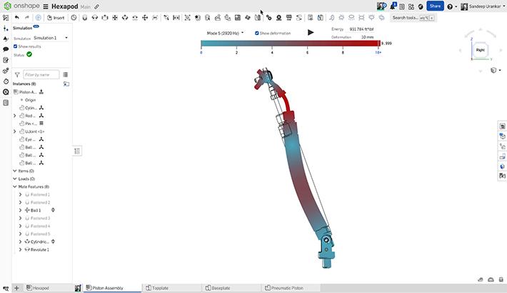
Mastering Kinematics: A Deeper Dive into Onshape Assemblies, Mates, and Simulation
12.11.2025 learn more
- Blog
- Evaluating Onshape
- Learning Center
AI in CAD: How Onshape Makes Intelligence Part of Your Daily Workflow
12.10.2025 learn more
- Blog
- Evaluating Onshape
- Assemblies
- Drawings
- Features
- Parts
- Sketches
- Branching & Merging
- Release Management
- Documents
- Collaboration
Onshape Explained: 17 Features That Define Cloud-Native CAD
12.05.2025 learn more
