
02:43
When using a top-down or Master model approach, it is common to design parts and subassemblies in their respective locations relative to the top-level assembly. To define these designed-in-place components in an Assembly, one option is to insert them relative to their origin (by clicking the checkmark button), Group them together, and Fix a component in place. This can also be automated by inserting the entire Part Studio as rigid. However, these workflows do not allow motion and do not always provide stability in higher-level assemblies, as highlighted in this Tech Tip.
As such, references to the origin may be more appropriate. This workflow may also be more familiar to users who have traditionally defined mates with reference geometry like planes and the origin.
The typical Insert, Group, and Fix process.
Mating Part Studio Entities at the Origin
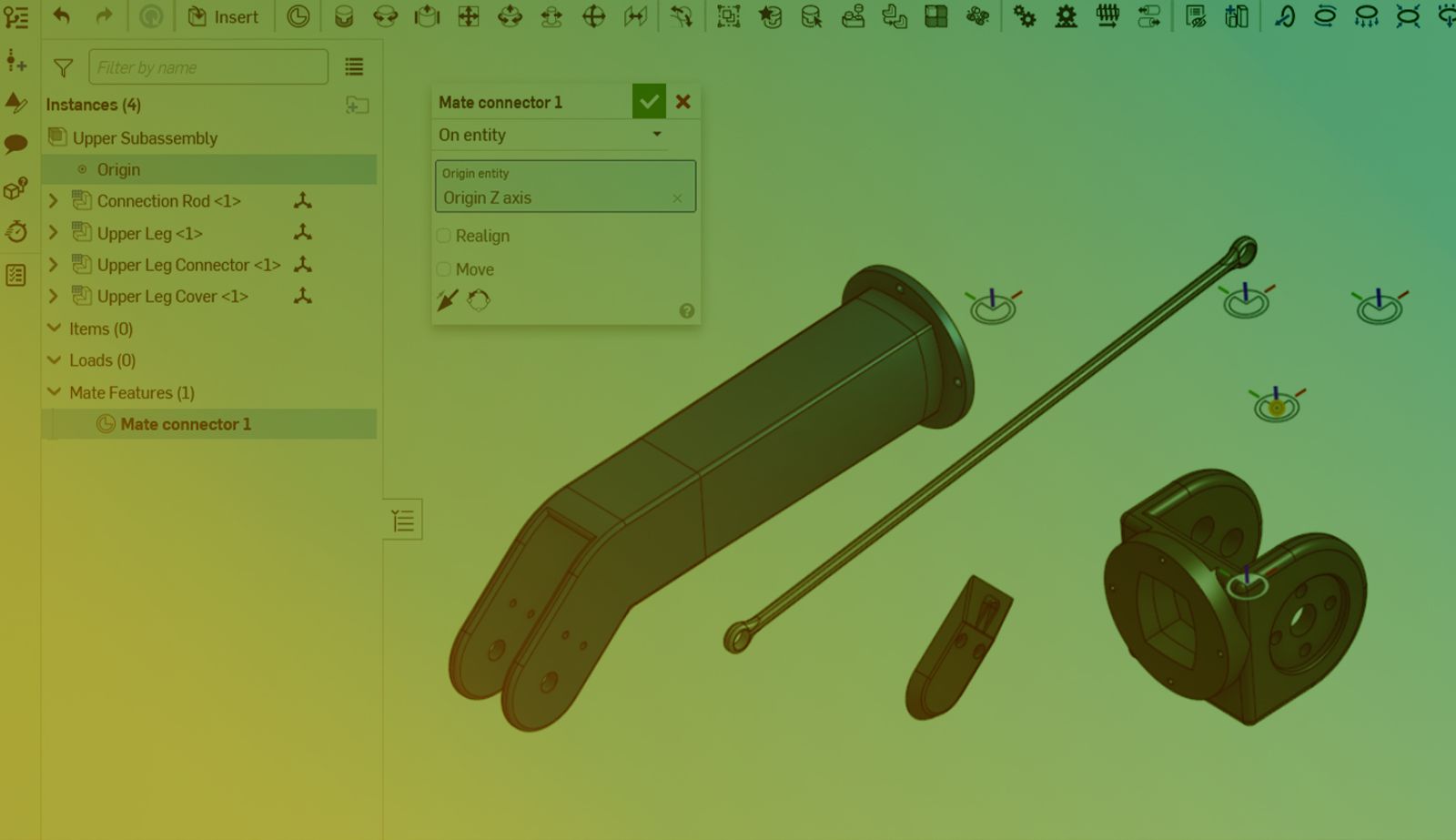
Create an explicit Mate connector to define reference geometry for a part, sketch, curve, or surface. To create a Mate connector at the origin in a Part Studio, select the origin in the graphics area or the Features list. Remember to specify the owner entity of the Mate connector by selecting the appropriate part or reference geometry.
Custom features offer automated ways to create Mate connectors in Part Studios, such as this linked feature.
Lastly, you can create a Mate connector at an instance’s origin in an Assembly tab by right-clicking the entity in the graphics area or the Assembly list and selecting Add Mate connector to instance origin.
Creating a single Mate connector, using a custom feature, and a Mate connector for a master sketch added in a top-level Assembly.
When inserted into an Assembly, entities carry along the explicit Mate connectors they own. This allows for rapid constraining of parts based on that reference geometry. Mate each of the entities to the Assembly origin. While the origin can be selected directly in a Mate dialog, creating an explicit Mate connector at the Assembly origin is more robust and efficient.
The insertion of a full Part Studio and another part. Mate one part to the origin directly, then undo. Make a Mate connector at the origin from the Assembly list. Mate all parts to that Mate connector, selecting it first in the graphics area and then in the Assembly list.
Mating Subassemblies at the Origin
Creating a Mate connector at the Assembly origin also provides a reference for mating in higher-level Assemblies. In addition to defining that Mate connector in the subassembly, as shown above, you can right-click on that subassembly in the higher-level Assembly to automatically generate that reference geometry.
With Mate connectors at Part Studio and Assembly origins, it is easy to constrain subassemblies relative to each other, and a Master model approach can be enforced throughout all levels of the design.
The creation of a Mate connector at the top level, mating of one subassembly to that Mate connector, insertion of a second subassembly, creation of the Mate connector by right-clicking and selecting Add Mate connector to instance origin in the context menu, and mating of the second subassembly.
To see a video of the above workflow, watch the following video:
Search for tutorials on these advanced features in the Onshape Learning Center.
The Onshape Learning Center
Take self-paced courses, read articles, or sign up for an instructor-led training session.
Latest Content
- Blog
- Becoming an Expert
- Assemblies
Built to Scale: Why Large Assemblies Don’t Slow Down in Onshape
07.16.2026 learn more- Blog
- News from Onshape @ PTC
- Artificial Intelligence
Onshape Labs: AI in CAD Guided by Designers, Driven by Innovation
07.15.2026 learn more- Blog
- Evaluating Onshape
- Data Management
- Collaboration
- Artificial Intelligence
How the Most Underrated CAD Feature Improves Design Workflows
07.09.2026 learn more