
01:15
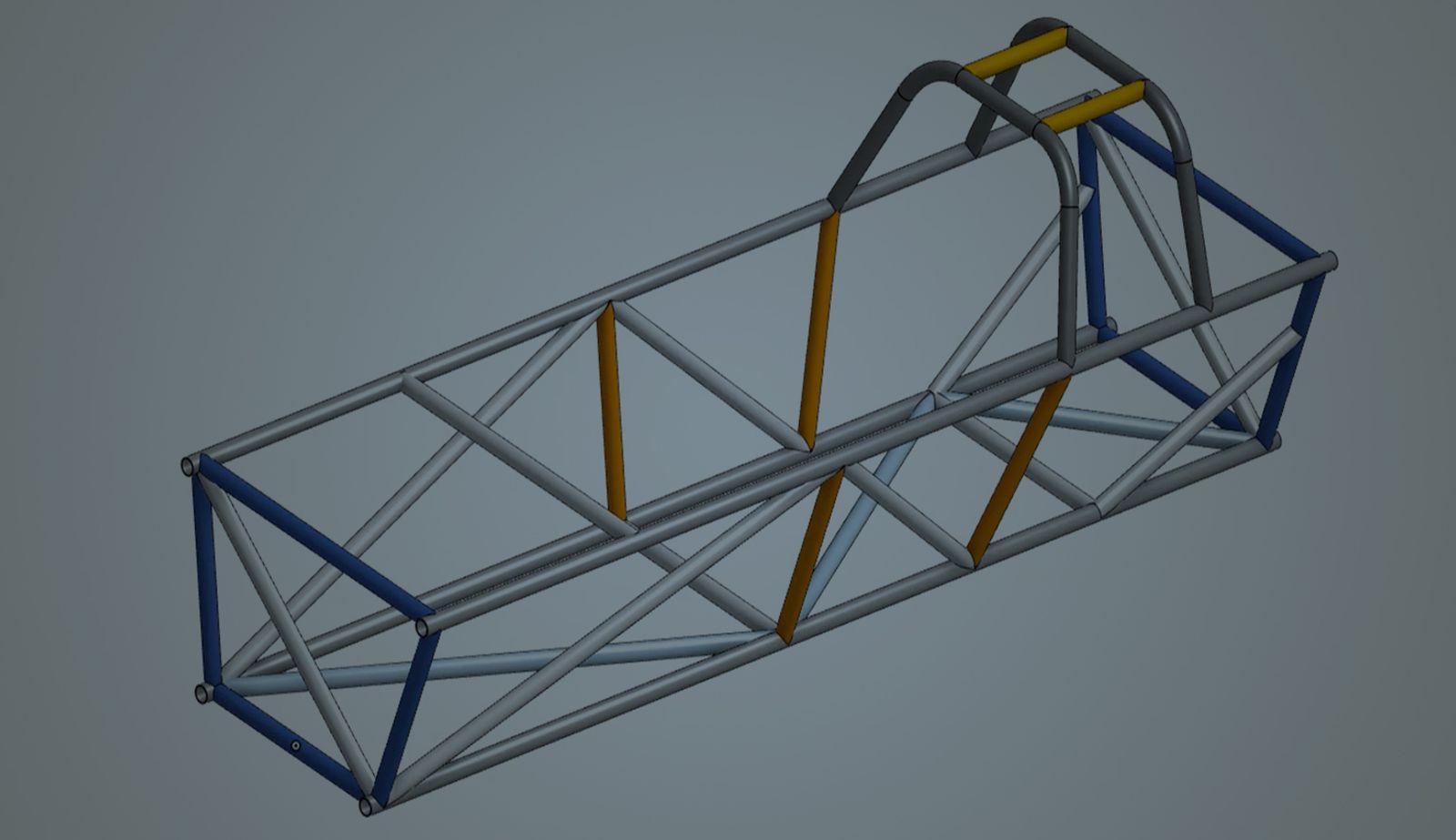
Onshape’s Frames functionality facilitates the efficient design of welded structures. Designers can specify a path to create groups of industry-standard tubes, channels, and beams with various corner treatment and trimming options.
However, building the underlying skeleton with multiple sketches and curves might take time and effort. But did you know the Frame tool also allows you to select the Edges of Parts and Surfaces? Using the edges of 3D parts and surfaces as skeleton geometry is a powerful and time-saving technique.
Use Solid Modeling to Build Skeleton Geometry
- Utilize traditional modeling tools such as Extrude and Fillet to represent and map out the necessary design.
- Use part faces to position sketches and build additional references.
- Split is a helpful tool for producing symmetric edges or calculating compound angles.
- The resultant solid models are robust and simplify visualizing the final design.
Generate the Frame
After completing the skeleton, construct the remaining geometry using the Frames toolset. Optionally, clean up the Part Studio by deleting the skeleton parts afterward.
LEARN: Check out the Frames Fundamentals Course in the Onshape Learning Center.
This technique is a highly effective way of creating structures. Incorporating this strategy with custom features makes complex geometry like a geodesic dome straightforward.
Watch the video below to see how it works in real-time.
Interested in learning more Onshape Tech Tips? You can review the most recent technical blogs here.
Friends Don’t Let Friends Use Old CAD!
Know a colleague who could benefit from our cloud-native, fully-featured collaborative design platform?
Latest Content
- Blog
- Becoming an Expert
- Assemblies
Built to Scale: Why Large Assemblies Don’t Slow Down in Onshape
07.16.2026 learn more- Blog
- News from Onshape @ PTC
- Artificial Intelligence
Onshape Labs: AI in CAD Guided by Designers, Driven by Innovation
07.15.2026 learn more- Blog
- Evaluating Onshape
- Data Management
- Collaboration
- Artificial Intelligence
How the Most Underrated CAD Feature Improves Design Workflows
07.09.2026 learn more