08:43
From the classroom to manufacturing enterprises, CNC machining and other digital fabrication technologies are augmenting education lesson plans and product development workflows. Digital fabrication is valuable in almost every industry.
But what are the basics of CNC machining? What do you have to understand about the machine to accurately translate computer design data into the physical world?
What is CNC programming? CNC programming is the process of creating a set of instructions that tell a computer numerical control (CNC) machine how to fabricate a part. It translates design specifications from CAD software into a language the CNC machine can understand and execute.
We’ve shared some basics about 3D printing. Now, here’s what you need to know about CNC machining.
Basics of CNC Machines and Tooling Geometry
A computer numerically controlled milling machine, commonly referred to as a CNC machine, transforms blocks of raw stock into finished parts by cutting away material. CNC machines are versatile tools that can produce complex parts with high precision and repeatability.
There are generally three axes to a milling machine:
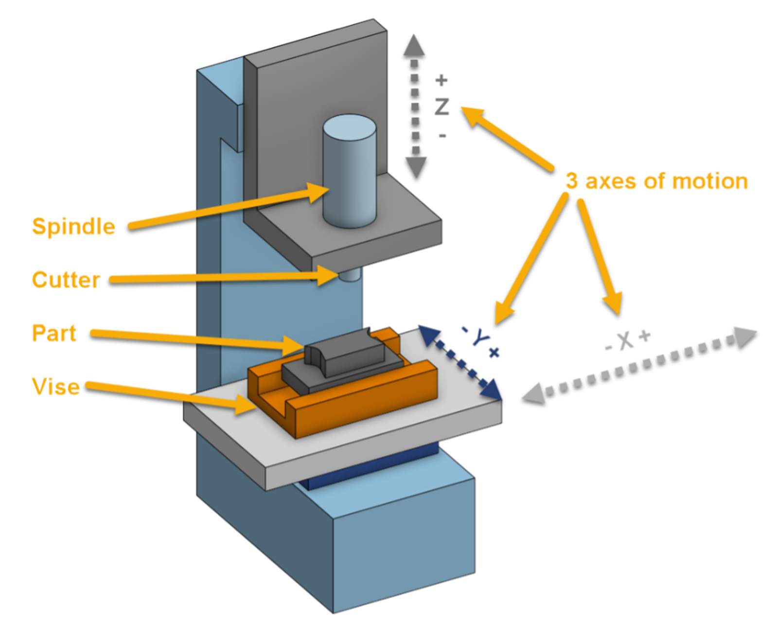
For the purposes of this discussion, we will consider the following directions when referring to the orientation of operations and tools:
- X axis: Left to Right (Sideways as viewed from the operator’s position)
- Y axis: Forwards and Backwards (As viewed from the operator’s position)
- Z axis: Up and Down (Vertical as viewed from the operator’s position)
These three axes of motion let the spindle, which spins a cutter at high speed, carve away material and leave behind nearly any shape desired.
The part being milled is held in a vise, which is in turn attached to the table of the CNC.
Designers typically use CNC CAD software to model the desired components to create parts from CNC machining. This software allows for precise 3D modeling and can generate the necessary files for CNC programming.
Types of CNC Machine Cutters
But, not all CNC machines are built the same way. There are different cutters or endmills. Here are some common types:
Flat Endmills: These are the most commonly available type of cutter. They’re efficient and cheap. Flat Endmills are ideally suited for machining of flat bottom cuts and vertical walls.
Bullnose Endmills: The Bullnose profile cutters are similar to Flat Endmills in that they share a common rectangular side profile but with an additional radius at the bottom corner of the flutes. They are great for quickly removing material while leaving a small bottom radius in pockets.
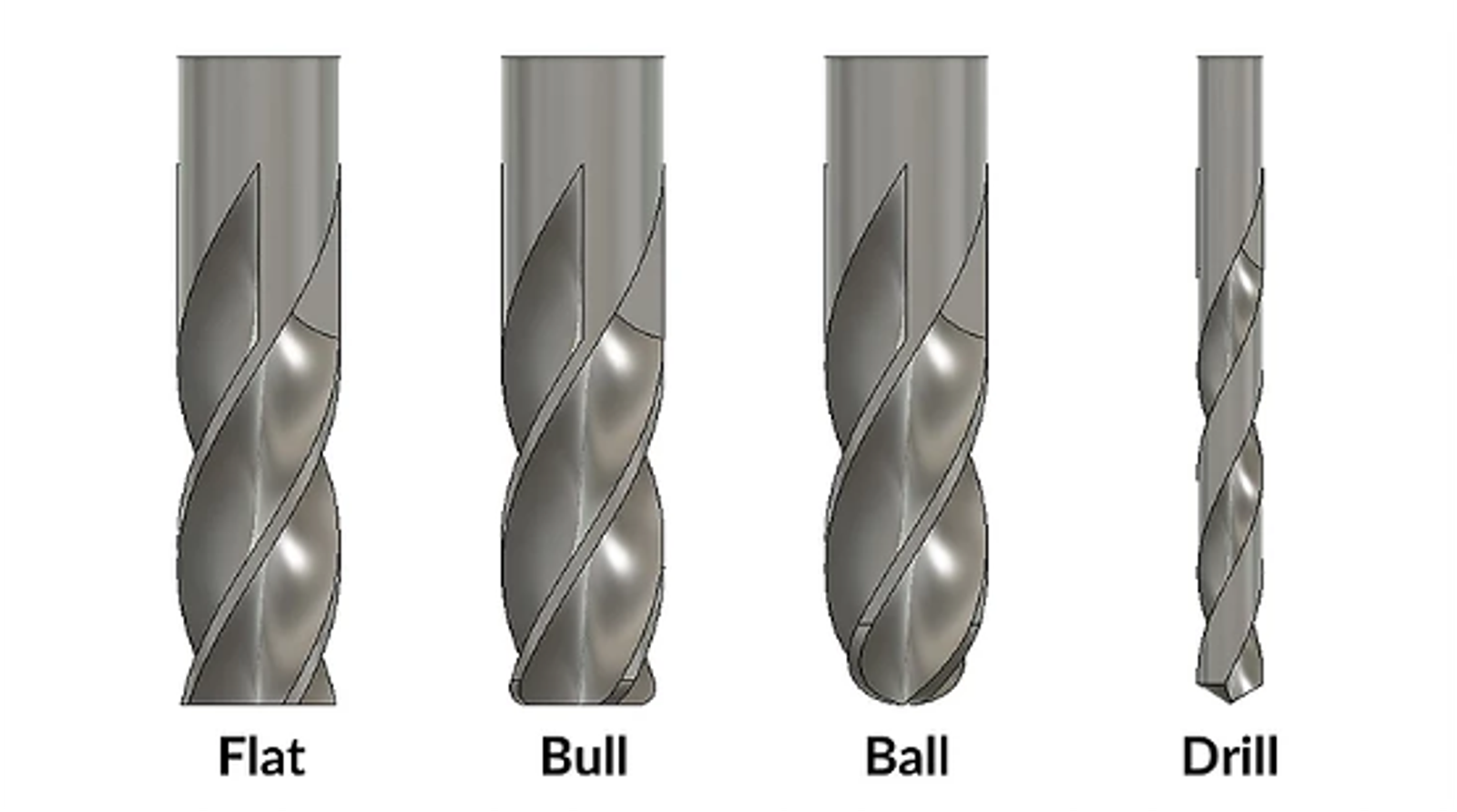
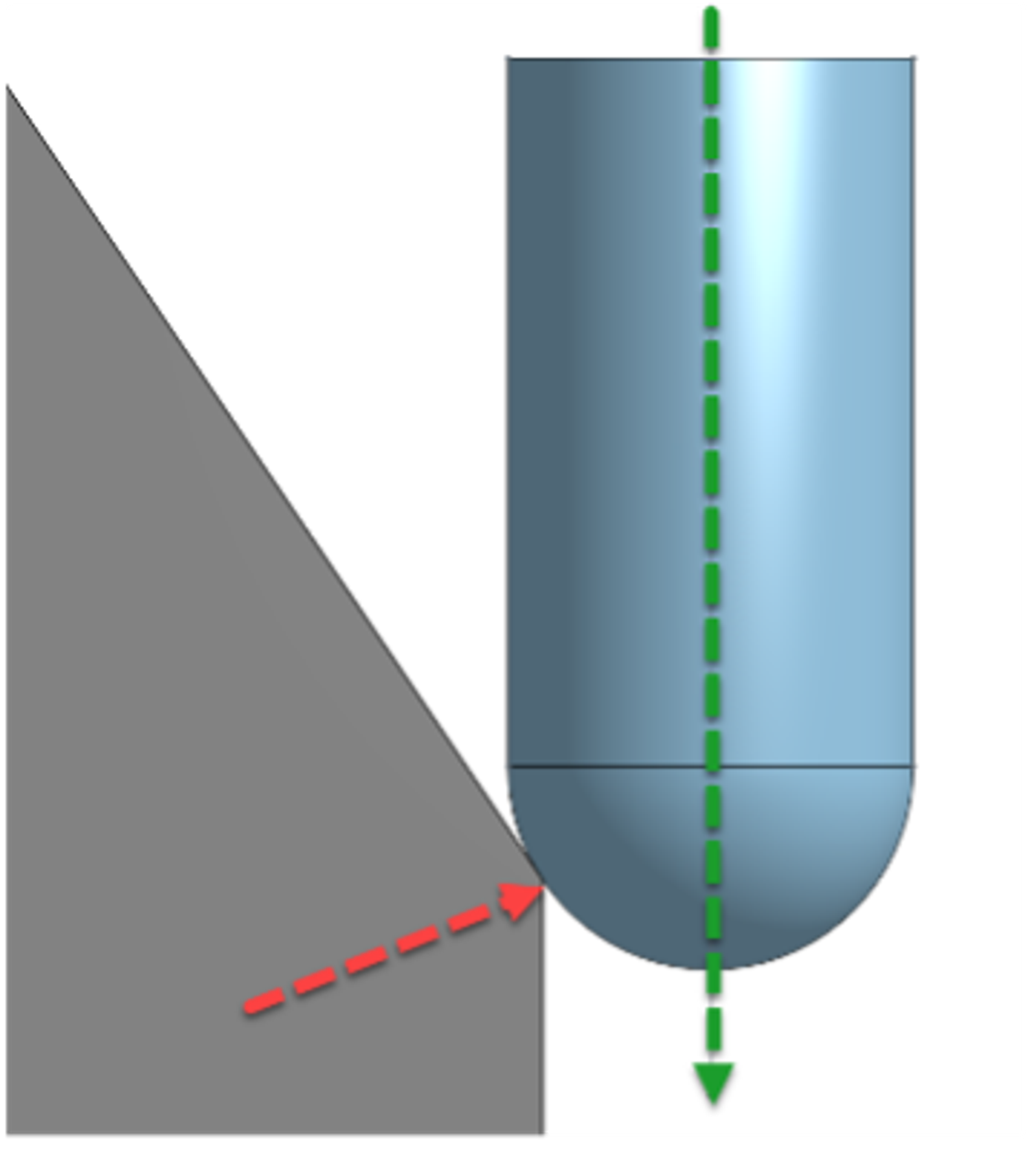
Ball Endmill: The Ball Endmill has a full radius at the bottom of the flutes. These cutters can be utilized for complex surfacing as the contact point between the tool and material surface is constantly changing with variations in the slope of the surface.
Drills: Drills are used exclusively for making vertical holes in parts. There is no side-to-side or horizontal motion of the tool when using drills. The finished size of the hole will be dictated by the diameter of the tool itself. Besides the diameter of the tool itself, another variable involved with drills is the angle of the drill point. Typical angles are 118° and 135°. Generally speaking, the 118° angle is used for softer materials such as wood or aluminum.
Subsequent operations (reaming, etc.) can alter the size of the hole, but those tools are not discussed in this blog post.
Additional Considerations Regarding Endmills: In addition to the side profile, it’s important to understand how the number of cutting edges, or flutes, are formed into the tool as viewed from the cutting end.
More flutes on a cutter restrict the amount of available space for the cut material (chips) to be removed. However, tools with a higher flute count perform better in harder materials.
The cutters shown below are center-cutting. This means that the sharp edge of the flute across the bottom of the mill extends all the way to the centerline of the tool.
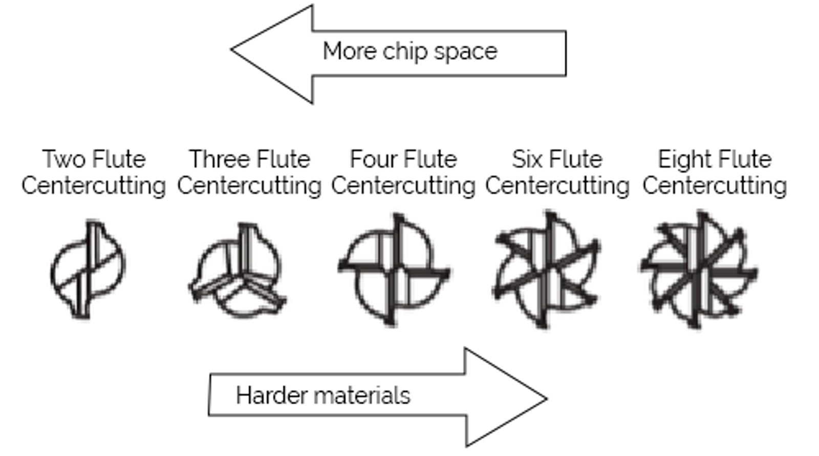
Keep these differences in mind when designing in CAD. Onshape, a cloud-native CAD platform, offers Custom Features that can help make your digital fabrication processes easier. Here are two features that can help you when designing for CNC manufacturing.
Sensor: Measures and compares geometric values. Make sure your tools will fit into corners.
Lighten: Removes material quickly from parts and can account for tool radius.
Why Tool Length Matters
But what about tool length?
Tool diameter, profile, and the number of flutes are important to consider. Another critical piece of information to consider is the tool length, especially the length exposed when the tool is clamped in the tool holder or spindle. This is commonly referred to as the tool stick out.
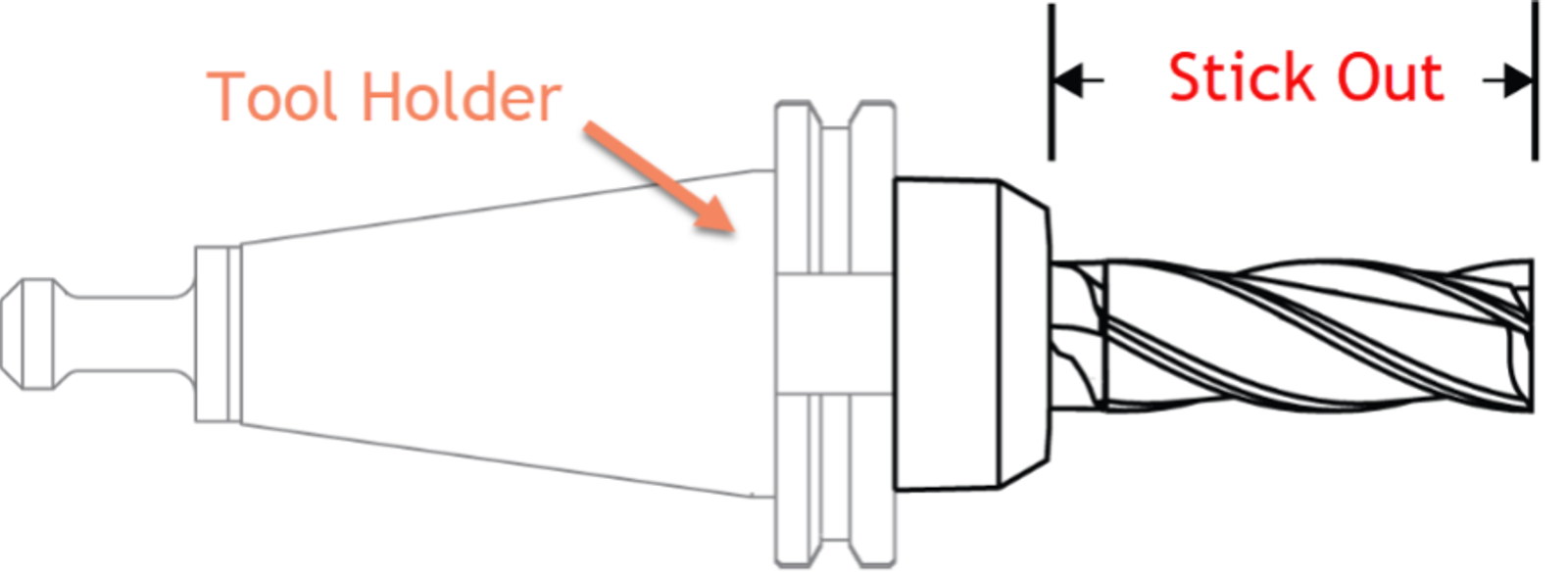
Figure 3 - Tool holder and stick out
Tools with a high ratio of stick-out length to diameter are described as having a high aspect ratio. As the side of a tool comes into engagement with the material while cutting, the forces involved work on the tool to create tool deflection. The higher the aspect ratio of the tool, the more deflection will be created.
Operations that create high side loading and therefore increased potential for tool deflection are:
- Deep pockets
- Large step down (changes in Z height) during operations
- High feed rates (the speed with which the X or Y location of the tool changes while cutting)
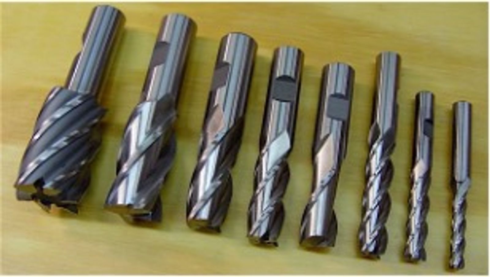
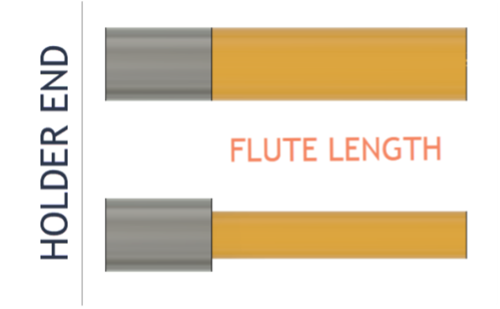
One final topic worth discussing regarding tool geometry is the length of cut (LOC) that a tool can achieve. Some end mills have flutes that terminate at the same diameter as the portion of the tool that engages in the holder. Others have a reduced or necked-down profile where the effective cutting diameter is less than the diameter of the holder:
There are more advanced machines with additional features and axes, but understanding the simple three-axis milling machine, different types of endmills, and tool length is an important first step to mastering manufacturing.
Design Considerations for Model Features
Above, we learned about the basics of CNC milling machines and different types of milling tools.
With that in mind we can start to look at different design considerations that can help make producing those parts easier and more efficient.
Vertical Internal Fillets
When considering internal fillets on vertical walls, we can see how the previously discussed topics impact our design process. Ideally, the height of the vertical wall should be less than the flute length of the tool, and the radius of the fillet should be larger than the radius of the available tooling.
Generally speaking, the fillet radius (R in the graphic) should be greater than 1/3 of the vertical wall height (H in the graphic).
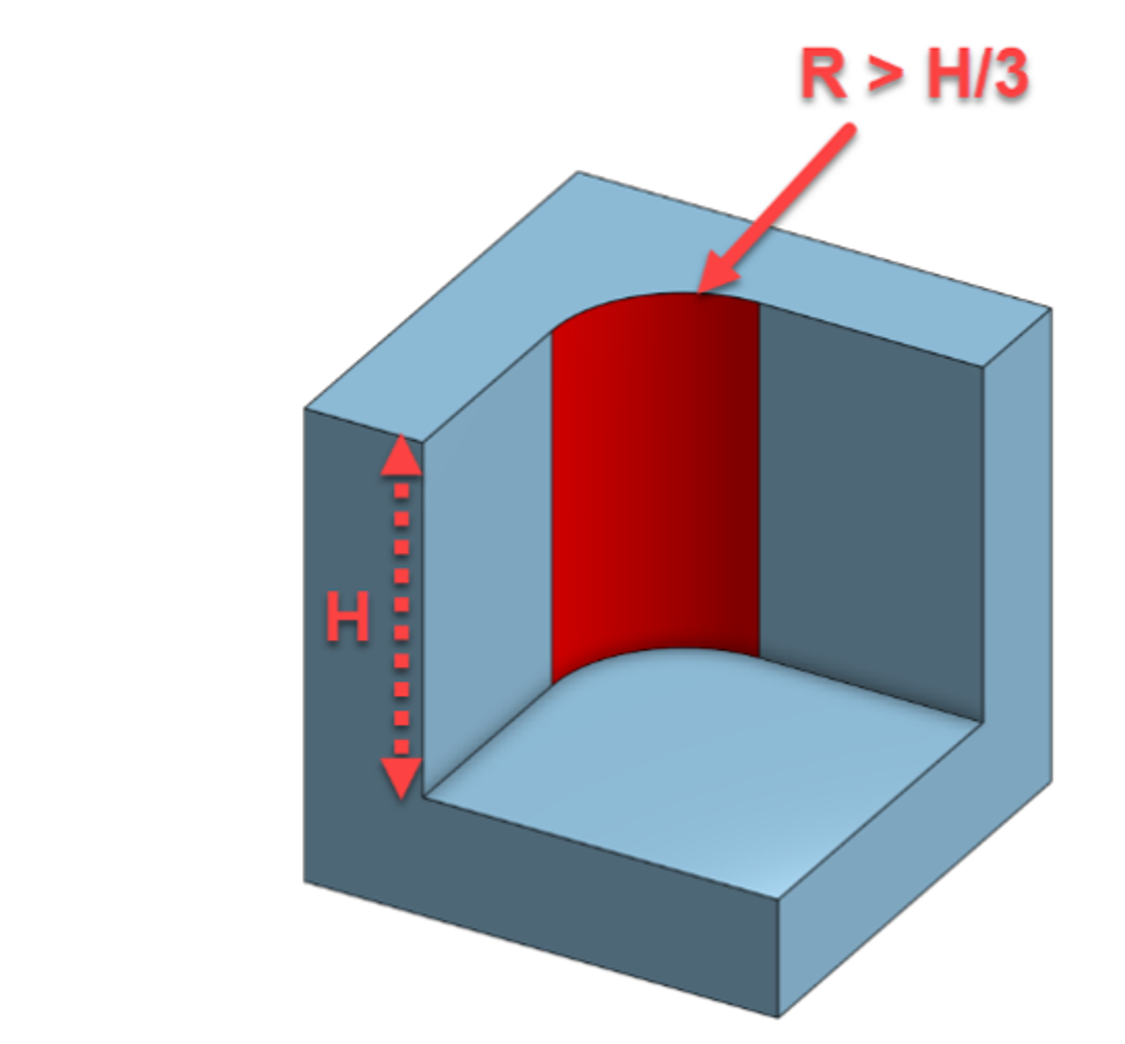
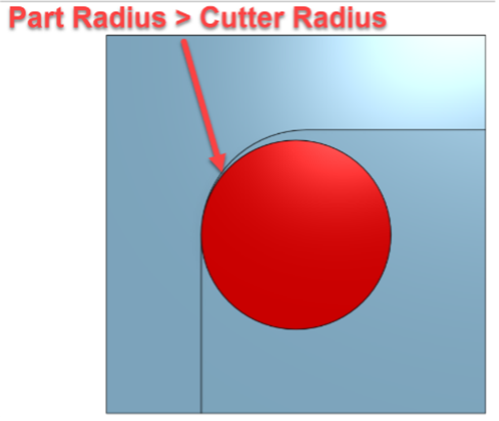
It is also important to ensure that the part fillet radius is greater than the radius of the tooling. This ensures that the amount of tools engaged with material stays more consistent.
If the tool radius is too close to the radius of the part, there will be a spike in tool engagement as the tool rounds the corner. This can lead to breaking tools or tool chattering (rapidly deflecting and bouncing), which will degrade the surface finish.
Bottom Edge Fillets
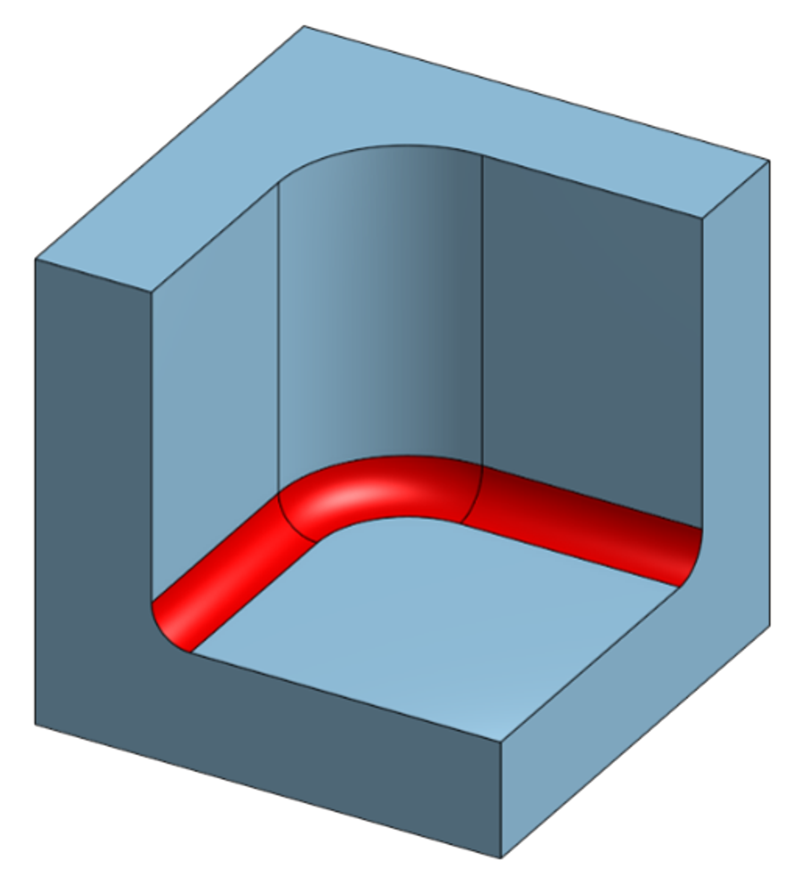
Often, the design requires internal fillets at the bottom of pockets or walls. In fact, parts without this feature can experience unplanned failure of the final assembly as a result of stress risers caused by a sharp corner.
It is advisable to make the following allowances in the design to minimize potential machining challenges when producing these parts.
If the pocket is for lightening a design, then the fillet may be able to be deleted from the design entirely
For fillets that are required, consider selecting a fillet radius that matches the corner or ball radius on multiple tools. This can allow the operator to use a suitable ball or bullnose endmill to machine the fillet.
If you are unsure of the corner radii available to the operators, it is better to select a larger fillet radius to allow for the use of larger diameter tooling.
External Fillets
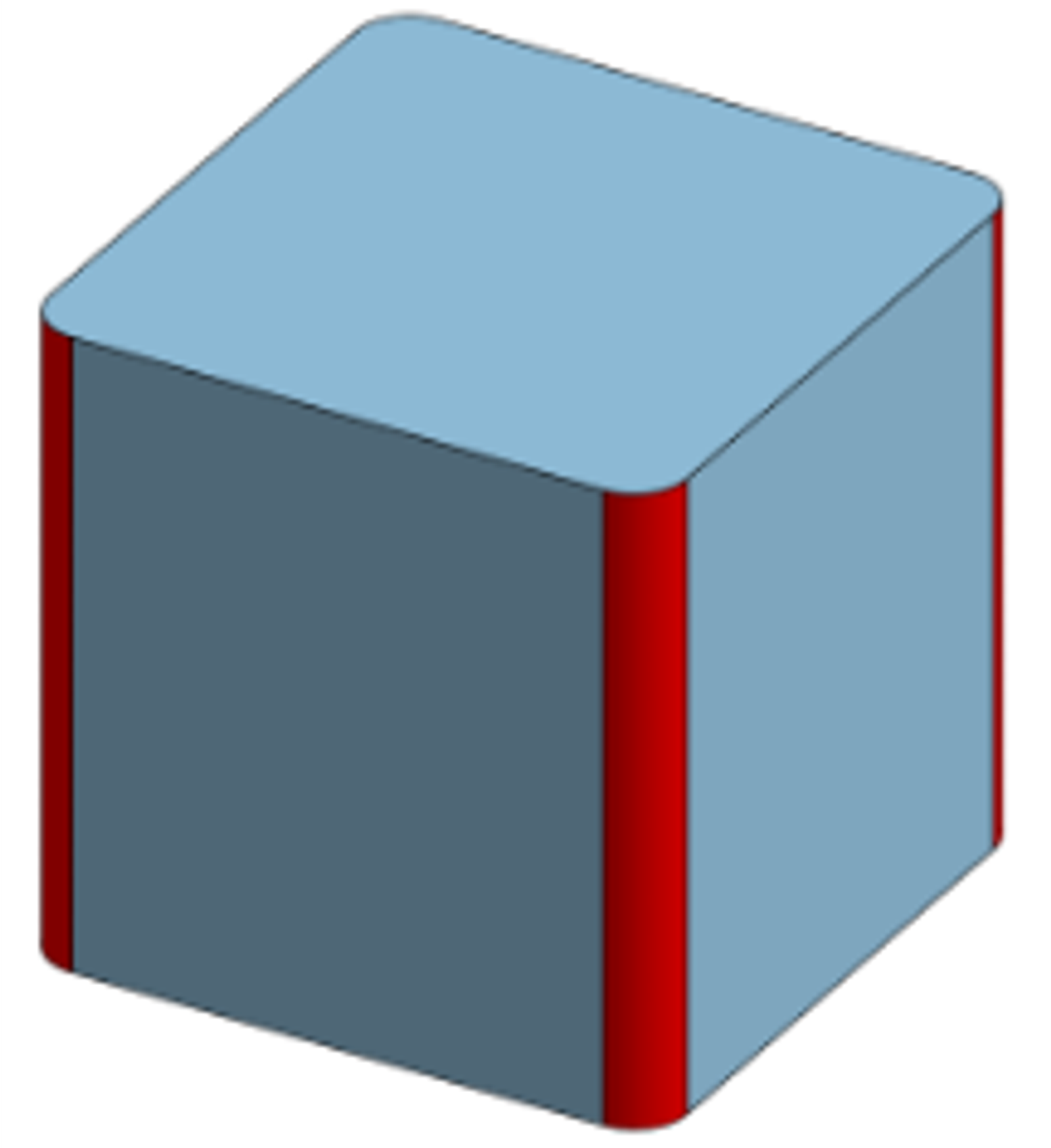
If the design intent allows, it is worth adding fillets to vertical external corners. This will allow for in-process deburring of those edges.
Since the toolpath will already be running around the profile of the part, these fillets can be added without appreciably increasing machining time (provided the fillets are of reasonable radius). The smaller radius selection is not as critical on external fillets as it is on internal ones. This is due to the way that the tool engages with the material. It is not experiencing a spike in loading or deflection on the outside corners.
Chamfering and Deburring
It is preferable to break the sharp edges on parts during the manufacturing process. Milling machines are capable of creating incredibly sharp edges, which can lead to workplace injury when production workers are handling parts.
Avoid using fillets to deburr the top edges of parts unless it is critical for preventing interference with mating components or some other important part of the design intent.
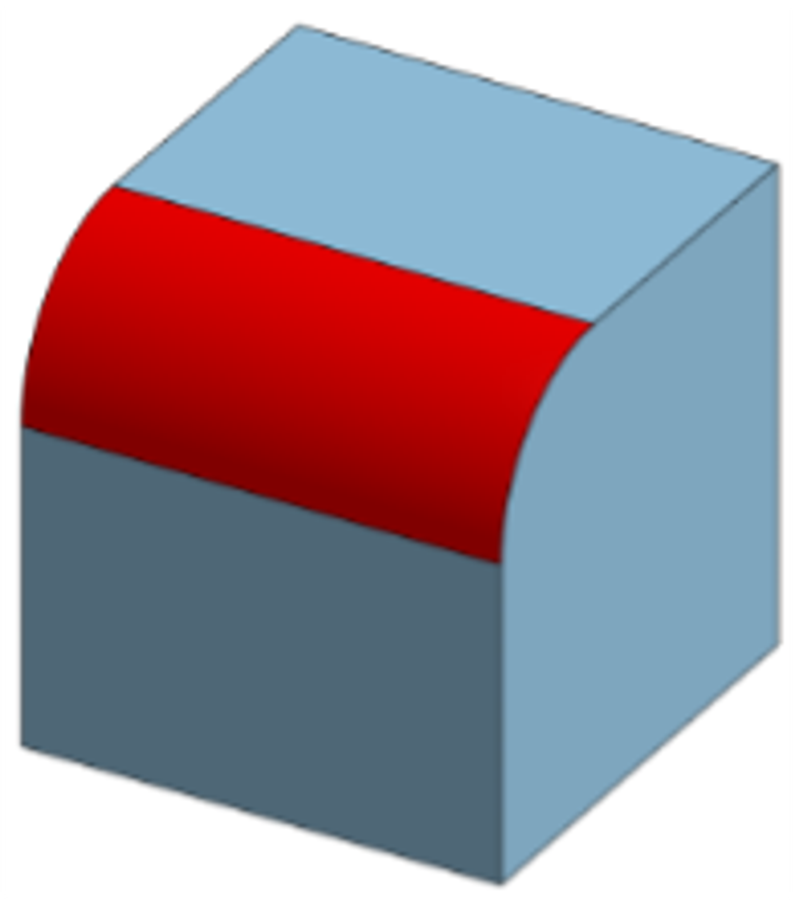
The tooling required to create these features in simple linear moves of the machine will need to be matched precisely to the radius (form tools). Form tools can be expensive to purchase or require excessive time to fabricate in-house.
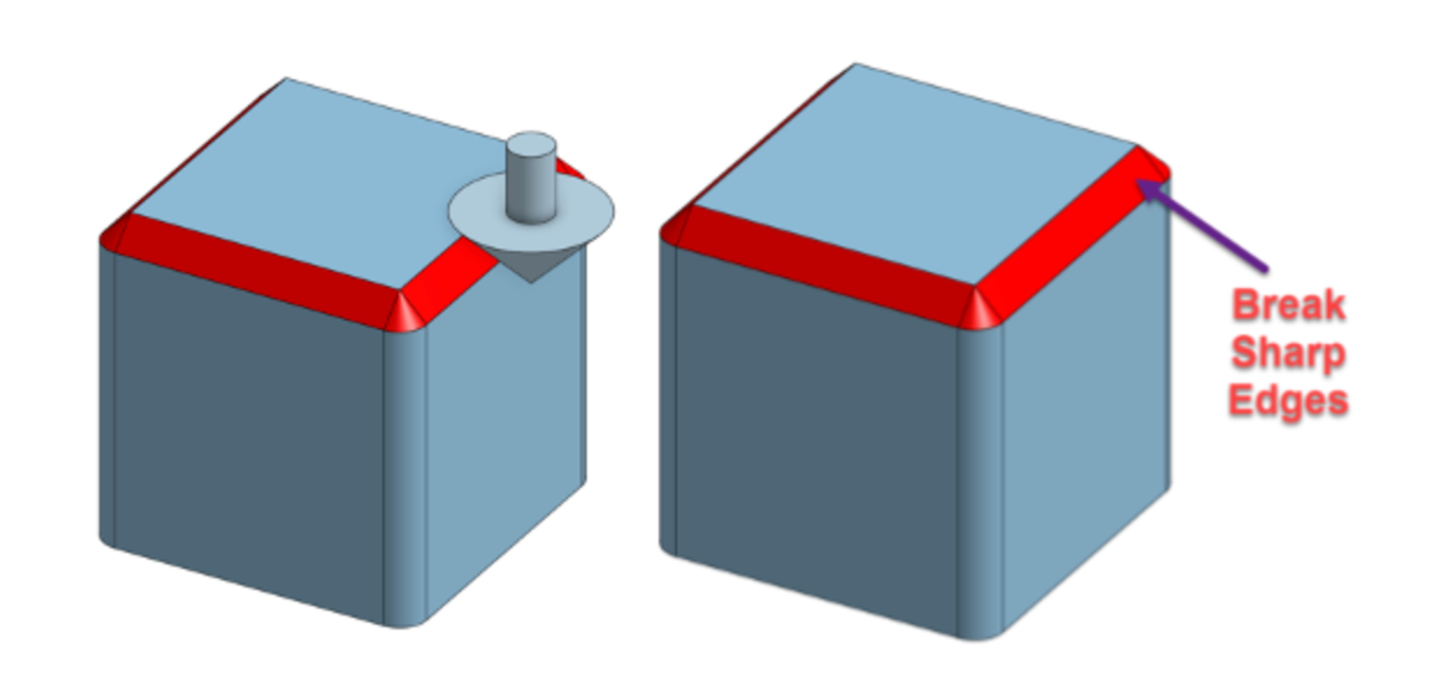
In these situations, a simple text callout on the drawing that states “BREAK SHARP EDGES” can reduce machining time by not holding the operator to a specifically toleranced dimension. This will also allow the operator to use readily available chamfering tools and negate the requirement of purchasing custom tooling.
Only model a chamfer if you need a specific toleranced dimension. In this case, it is recommended to use a 45-degree chamfer. This is a very commonly available chamfering tool. Different widths of chamfers can be produced with the same tool depending on where the toolpath is programmed.
Using Onshape for CNC Milling
Onshape, as a cloud-native CAD system with built-in PDM, offers seamless integration with various CAM software solutions that can be found in the Onshape App Store. This integration allows users to easily transition from design to manufacturing, streamlining the CNC programming process and enhancing overall efficiency in product development.
The Onshape team also has a number of resources to get you started with CAD software, whether you’re an educator implementing a project-based learning plan or a company looking for ways to improve production workflows.
Try Onshape Today
Head to our sign-up page to choose the right CAD plan for you and your team.
(Dave Lapthorne is an Onshape Education Technical Services Engineer.)
Latest Content

- Case Study
- Robotics
Saga Robotics: Powering the Future of Sustainable Farming with Cloud-Native Onshape
01.05.2026 learn more
- Blog
- Becoming an Expert
- Sheet Metal
Two Views, One Model: Faster Sheet Metal Design in Onshape
02.12.2026 learn more
- Blog
- Customers & Case Studies
- Collaboration
- Consumer Products
RigStrips Boosts Design Speed Using Onshape's Collaborative Tools
02.11.2026 learn more
- Blog
- Becoming an Expert
- Features
- Data Management
How Onshape's Repair Tool Fixes Broken References
01.29.2026 learn more


