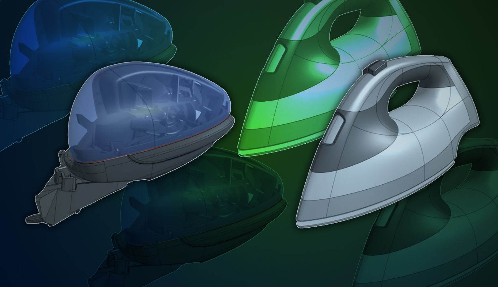
Surface design is a powerful technique for creating complex, freeform shapes in 3D CAD software. While many designers primarily work with solid modeling tools, understanding surface modeling can significantly expand your capabilities and open up new possibilities for your designs. 

In this blog, explore the world of Onshape surface modeling and learn the 10 golden rules of surface design.

What is Surface Modeling vs. Solid Modeling?

Before diving into the specifics of surface modeling Onshape, it's important to understand how it differs from solid modeling. Surface modeling is commonly used to create complex freeform shapes, but its applications extend far beyond that. While most of your modeling work might involve prismatic shapes, surface modeling techniques can be valuable tools even in solid modeling scenarios, sometimes in just one or two features.

Many designers view surface and solid modeling as mutually exclusive approaches, but it’s crucial to understand that they’re often interwoven. Rather than thinking of it as an either-or decision, consider how you can combine both techniques to achieve your design goals. 

Additionally, Onshape’s parametric modeling capabilities allow you to build design intent into your surface models, making it easier to accommodate changes and collaborate with mechanical engineers.

Onshape’s Robust Suite of Surfacing Tools
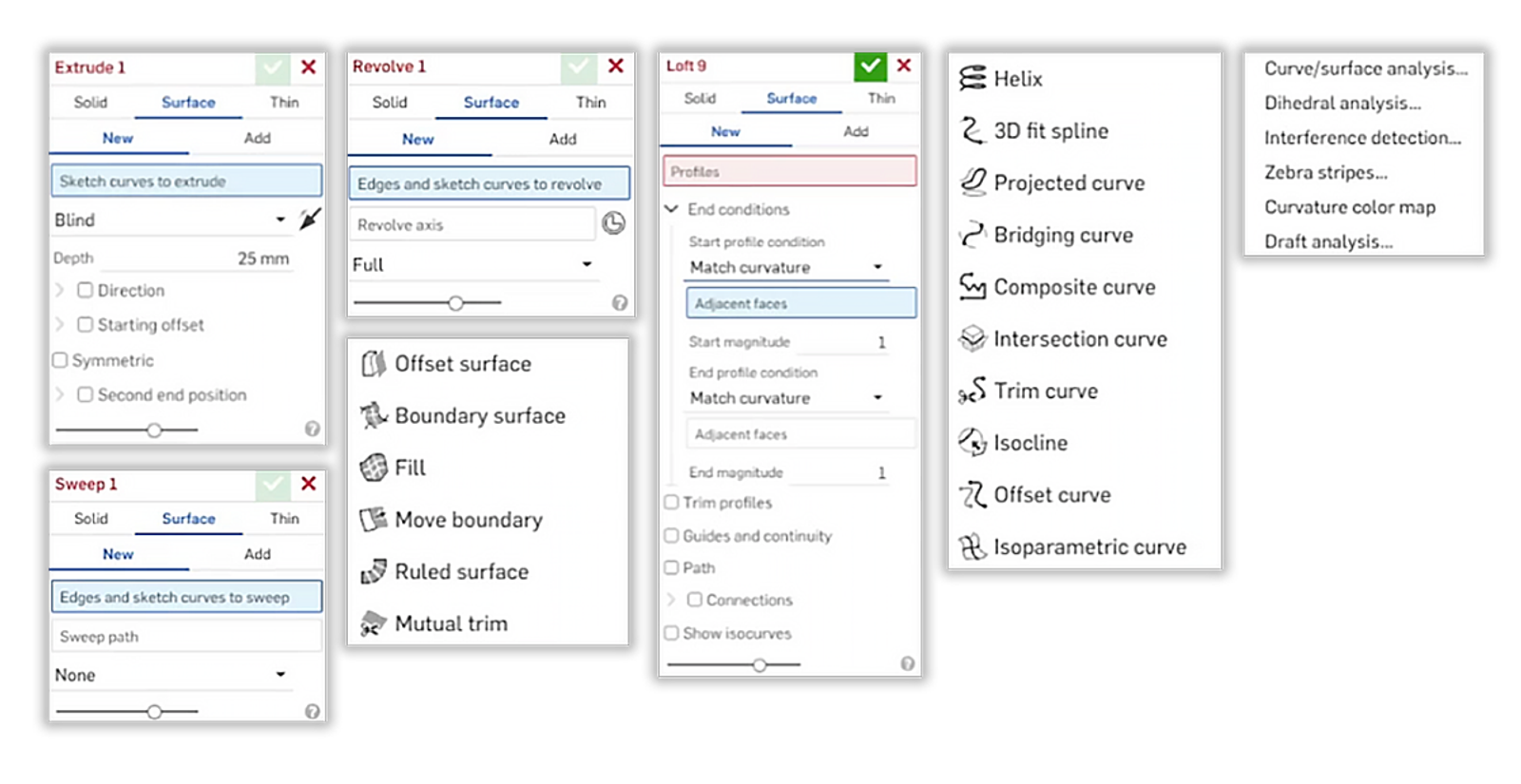
Onshape Surfacing tools

Onshape offers a comprehensive set of surface modeling tools that continue to grow and improve. At the core, you'll find familiar operations like Extrude, Revolve, Sweep, and Loft. However, Onshape has taken a unique approach by integrating these tools into unified features. Unlike some CAD systems that have separate commands for surface extrude, surface loft, and swept loft, Onshape provides a single sweep feature that can create solid, surface, or thin geometry.

This integrated approach simplifies the workflow while maintaining flexibility. When you use these core features, you'll find options to create surfaces or solids within the same command, streamlining your design process.

Beyond these foundational tools, Onshape’s surface modeling capabilities are organized into four main categories:

  1. Wireframe: Tools for creating and manipulating curves and sketches that form the basis of your surface models.

  2. Surfaces: Features for generating and modifying complex surface geometry.

  3. Manipulations: Commands for editing and refining existing surfaces.

  4. Diagnostics: Analysis tools to evaluate the quality and continuity of your surface models.
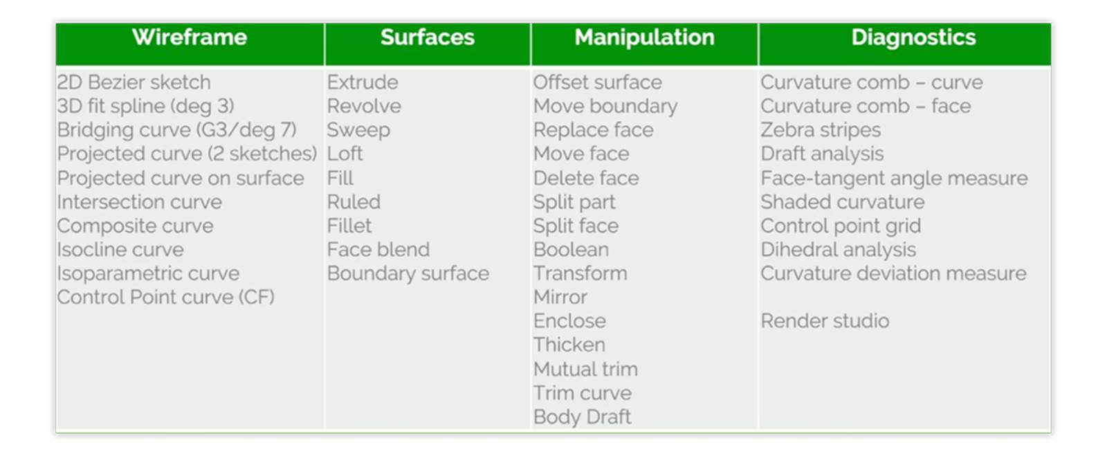
Surfacing toolsets in four categories

The Onshape development team has been actively expanding this toolset, with over 38 new surface-related features added in the past two years alone. This commitment to enhancing surface design capabilities means that Onshape users have access to a robust and ever-growing set of tools for tackling even the most challenging surface modeling tasks.

10 Golden Rules for Surface Modeling Onshape

To help you create high-quality surface models in Onshape, follow these 10 golden rules:

  1. Create a good flow of control points: Ensure that the control points defining your surfaces flow smoothly and evenly across your model.

  2. Use the minimum number of control points: Start with fewer control points and increase only as needed to achieve the desired shape.

  3. Use single-span curves when possible: Single-span curves often result in cleaner, more predictable surface behavior.

  4. Ensure tangency across centerlines: Exploit symmetry whenever possible to maintain smooth transitions and reduce modeling complexity.

  5. Aim to create four-sided surfaces: Four-sided surfaces are generally easier to work with and produce cleaner results. The preference order for surface creation tools is: Boundary surface, Loft, Fill.

  6. Trim to achieve n-sided surfaces: When necessary, use trimming operations to create surfaces with more than four sides.

  7. Build to theoretical edges: Create larger surfaces initially, then trim them back to manage transitions and blends.

  8. Set construction tolerances at the start of modeling: Establish your tolerances early to ensure consistency throughout the design process.

  9. Avoid building from trimmed edges: Building on trimmed edges can lead to stability issues and unexpected behavior when the model is modified.

  10. Match curves on opposite sides: This rule ties back to the first, emphasizing the importance of maintaining a smooth flow of control points across your entire model.

Applying the Golden Rules: Real-World Examples

Let's explore how these golden rules apply to real-world surface modeling scenarios in Onshape:

Example 1: First Build Slab Surfaces

Well, let's dive into an example. I'd like to dive into this engine cover. This is a model Greg put together. It's an engine cover for an RC car.

It has some aesthetically defined features, and it also has some mechanically defined features, which we'll cover later on. How would you go about building this using surface modeling tools? And what are some techniques or tips that we can learn for building something like this?

Using Onshape surfacing? One of the first things I would stress, and it's been mentioned before, is the golden rules one through five and seven: wireframe layouts, curve building, modeling to theoretical edges.

This initial shape is built using those tools. Now, notice this is half of the engine cover. So we're using symmetry. We're using a wireframe layout that consists of both 2D sketches and 3D curves. So we're building that wireframe layout using a combination of both 2D sketches and 3D curves.

And we're building it out to theoretical edges. It's important to stress this - I'm just going to jump back one slide here - it's not a sharp corner in the corner of the engine cover, but we're building to that sharp corner. And then we're going to trim back and manage that transition as a separate feature. When we talk about building to theoretical edges, that's what we mean. Extend those surfaces out until they meet at that theoretical point and then trim them back to manage transitions around the surrounding bases.

So what does this look like in practice? Well, let's dive into a quick example, and what I'd like to do is jump into the slabs example of this. First, start with the wireframe.

I stress this because, as I've said a handful of times, the curves are really the foundation of a good surface model. If you spend the energy in building out well-constructed curves, you build a foundation to build your surface model well, right? That behaves well to change, that has smooth continuity and all the things that we really desire in a good surface model.

Now, this, I would like to stress, is actually a combination, as I mentioned in the slide there, of 2D sketches and 3D curves. This actually uses a very neat feature called control point curve. If you're into building surface modeling and you're not using control point curve, definitely add it to your toolbar. I can't recommend it enough. There are a number of custom features I'll highlight in just a bit, but control point curve is one of the more useful ones for sure.

What we've done here is essentially build a handful of 2D sketches and a couple of 3D curves that define the wireframe for that initial slab series of faces. What I'd like to point out, a good organizational technique going back to our past presentation on design intent, is to notice the color of the geometry. The 2D sketches are blue. The 3D curves are this orange color. It's a very good practice. It's actually something we recently added, to delineate those things with colors.

If you delineate your geometry, your curves from your sketches with colors, it makes looking at geometry like this, which is a wireframe layout of a half section of this engine cover, easy to understand. If everything's the same color and you start adding more and more sketch geometry and curves, it can be very difficult to discern which is which. So one big tip that I have for you is to add those colors to define whatever color scheme you define as most useful to you.

Define the colors of the geometry as a way of delineating them and as a way of, at a glance, like we're looking at it here, I can tell the difference between the 2D sketch geometry and the 3D curves. While this is only a handful of pieces of geometry, if this had dozens of pieces of geometry, or even hundreds, you would really struggle to discern from the wireframe fog what is what. That's where I think colors are really applicable.

Now, the other thing I really want to stress is that this is the beginning of this engine cover model. We are building the wireframe for all of the surfaces that will follow from it. So, if I roll down into the slabs folder, you'll see we do a handful of features and a handful of boundary surfaces. The boundary surfaces are just using the edges of the 2D sketch and the 3D curves, the control point curves in this example.

So we have two boundary surfaces, a loft for that transition phase, and then a boundary surface here on the end. All we're really doing here is defining those sketches and curves. Once we have that, it's just a matter of selecting the boundary surface and then selecting the individual edges that make up each boundary surface. You can think of surface modeling a lot of times, not always, as a process of building a model face by face.

That's really what we're doing here. We're constructing these using a series of boundary surfaces or loft features. But the most important takeaway from this example that I would give you is to construct, spend extra energy constructing that wireframe layout well, building the proper design intent into the wireframe layout, and then the boundary surfaces will just sit on top of that. Curves are everything. That's something I'm going to say a few times here today.

In this example of an RC car engine cover, we apply rules #1-5 and #7. The design begins with a carefully constructed wireframe layout using both 2D sketches and 3D curves. By focusing on creating a clean foundation with well-placed control points and single-span curves, we set the stage for high-quality surfaces. The initial surfaces are built larger than necessary, following rule #7, allowing for precise trimming and blending later in the process.

Example 2: Using the Bridging Curve

So the next tip: use bridging curve. Bridging curve is a hugely powerful tool and one that I think is underused even by surface modeling experts because it has so many applications and so many potential uses. But there's a handful of things I would point out about this. Bridging curve is a very important tool for building those wireframe transitions between faces.

You can see in this example we've essentially taken those slab surfaces that I've constructed that make up that half of the engine cover, and we've trimmed them back. I'm going to show you in a moment a few tips that we have, a few techniques that we have around trimming those surfaces, but we overbuild, trim back to the point of transition, and then we build those transitions using bridging curve.

Bridging curve has all kinds of really neat features. It has the ability to match curvature and even flow with G3 continuity. So you can define as smooth a transition as you could possibly want using bridging curve. It creates a single span Bezier curve. That's an important thing. That's one of the reasons we emphasize bridging curve, because they tend to be very clean curves. The resulting curve tends to be very clean. And so it makes a great boundary for a boundary surface or a path or a profile, even, for things like a loft.

Important to any parametric CAD system, but important to building good models, it's parametrically driven. It's referencing the geometry that's surrounding it. So if the surrounding geometry changes, naturally your bridging curve will update. It will update in a way that's predictable. So I would say it's important to keep in mind, as you're doing this, the transitions are especially important.

Let's take a look at an example of this. I'm going to jump into my next tab just a few steps forward. There are a few things I would point out about this, just to set it up a little bit before we dive into the nuances of the bridging curve. If I roll back just a bit here, this is essentially a similar surface to what we had in the last example.

There are explicitly modeled transitions. These are just surfaces that are defined here to manage those blends between the faces. But what we're doing is we're using that geometry to manage that transition. So you can see here I have a projected curve, and this projected curve is actually used to define the point that I want to trim back. It's kind of the point where this transition begins. So I've created a parametric curve, but I'm really just using the parametric curve to define the point that I want to define to start that transition.

Then I'm using the isoparametric curve feature to actually create the curve that will be used to generate, in this case, a bridging curve. The reason I stress this, and you'll hear me say this at a handful of points, is you want to avoid using projected curved edges, if possible. In other words, you project a curve, maybe you split the geometry around a projected curve, and then you use that downstream. It's just the nature of projected curves that they tend to create very messy edges.

One of the more common things that we see in surface modeling is to use a projected curve, project onto a surface, split using that projected curve, and then build on top of that split edge using a series of features. I really recommend avoiding that if possible. If you look at the resulting edge using a curve analysis, which I'll show you in just a moment, you'll see that they tend to create very messy, not very clean, resulting trimmed edges.

When in doubt, and if possible, use isoparametric curve when you can, because the isoparametric curve is actually at that surrounding geometry. It's not a projection onto it. It's actually using the geometry of the surface itself to define that. So in this example, it's actually a common workflow where we use projected curve just to define where that point is. And then we use the resulting point to generate an isoparametric curve.

The resulting geometry, this edge that's defined with the isoparametric curve, is much cleaner than if we had used some other projection technique. So, one big tip that I have for you: when in doubt, try to use isoparametric curves in favor of projected curves to split geometry. The resulting curve is a lot cleaner.

So that's essentially what we've done here. We've taken that slab model that you saw just a moment ago. We've trimmed it back using a combination of projected curves and isoparametric curve. And now we need to build the transition or the blend between these two surfaces. To accomplish this, like I mentioned before, very importantly, we use bridging curves. You can see here's bridging curve one. Zoom in a bit.

This is a transition between these two faces, and we get that single span Bezier curve that has a smooth transition between the resulting faces. And importantly, it will parametrically update. We built a handful of these. Essentially, what we're doing is building a handful of bridging curves, three in this example, to define the transition, a wireframe layout of that transition.

Even beyond those initial stages of building the wireframe of the overall shape, you're going to use wireframe layouts in a lot of different places, and blends and bridging curves are very good examples of that, where you're going to build a handful of bridging curves that define the boundaries of the blend and then use that to build a boundary surface result. It's very easy for you to construct continuous surfaces in this case using something like a bridging curve.

Now, not to dive too deep into bridging curve, because you could spend a fair amount of time on bridging curve alone, but it's a very powerful feature that has really excellent matching options. So when you're really concerned about continuity between surfaces or between the surrounding geometry, this is one of the tools you want to use.

It has, of course, match position and tangency. It also has curvature continuity and flow, a true G3 continuity. So if you're really concerned about the transition and smoothness in the transition, bridging curve can be a very powerful tool to adopt in these kinds of workflows.

Now, I don't want to spend too much time on it, but if you haven't already dived into bridging curve, and you're really looking to do some advanced surface modeling, bridging curve is going to be, I promise, one of your favorite features.

So that is bridging curve and using bridging curve in situations to manage blends. Now we've taken our wireframe, built the slab surfaces on top of it, trimmed back those slab surfaces, and used bridging curves to build that wireframe layout of the blend. Then we can use tools like boundary surface in this example to build those boundary surfaces. But again, we're really building all of this on top of that wireframe layout of curves. Whether those curves are bridging curves or control point curves, or even 2D sketches like Bezier curves in a 2D sketch, they're all applicable, but focus on the curves. And I think that's one of the biggest messages that I would take away from today.

Bridging curves are powerful tools for creating smooth transitions between surfaces. This example demonstrates the application of rules #1-3. By using bridging curves with carefully controlled continuity settings, we can create seamless blends between complex surface patches while maintaining a minimal number of control points.

Example 3: Clean Edges, Even After Trimming

I mentioned this just briefly, but you really want to, when trimming, be very specific about what you're using to trim with. And I mentioned an example of this, avoiding the projected curve. I'll show you an example of what the resulting geometry can look like in a worst-case scenario when using projection and then split. Like I mentioned before, it tends to create kind of messy edges. Use isoparametric curves when possible. I showed you that example. We're really just using projected to find the point where that transition starts. And then we're using isoparametric curve to actually generate the curve that will be used for the resulting bridging curves and subsequent boundary surfaces.

So keep in mind, when you're building geometry in general, be careful of project split, using projected curve onto a surface and splitting with that surface. I'm not saying it can't be used, but you just want to avoid those kinds of situations if possible. And frankly, isoparametric curve is a better tool to accomplish that same end result.

Another very important tip in this same sphere is you want to avoid, when possible, building lots of subsequent features based on a trim or after a trim, but especially a trim that was built using a projection. Because what you're doing is increasing the likelihood that there's a downstream problem. And we all know when you have a downstream problem, if you go back way up in the feature list and make modifications, you can have this potential to generate all of these downstream problems as a result of that. So one big bit of advice is be cautious about building on top of trimmed edges and be very deliberate when you do it, and try to avoid it if possible. In general, I think that you'll end up with a lot cleaner models if that's true.

This example highlights the importance of rules #6 and #9. When trimming surfaces, it's crucial to maintain clean, well-defined edges. By using techniques like isoparametric curves instead of projected curves for trimming operations, we can achieve cleaner results that are less likely to cause issues in downstream modeling operations.

Example 4: Diagnostics

So, the next tip, and this is an important one, and I would say this about any surface modeling that you do, and it ties very much into the theme of not building too far into the model before understanding you have a problem. And that is diagnostics. As you're building, Onshape has a whole suite of diagnostic tools. The hydraulic analysis, curvature maps, reflections, flows across boundaries. You can determine that, you can define the number of CPs, the control points, and the location of those control points within a surface. There's even a custom feature that allows you to do that.

But the most important tip that I would give you is constantly be diagnosing the surfaces and the curves that you're building. And some of these tools you can just leave on, and I would recommend leaving them on. Zebra stripes, for instance. If you're concerned about continuity, you can just leave that on. The curvature maps as well. And you make modifications while those are active, which is a really powerful tool for making sure your transitions are smooth or your curvature is what you're expecting.

But the thing you want to avoid is building lots of features on top of geometry that is, for whatever reason, not what you want. And that's just parametric CAD in general. But if you have a trimmed edge that has all these jagged definitions to it, and then you start to build a whole bunch of features off of that and then later realize you have to trim or change that trimmed edge, you have a lot of cleanup work in redefining the parametric relationships between those subsequent features and the trimmed edge.

And that applies to everything. If you don't have a smooth transition between the two faces and then you go build a dozen features on top of that base and then realize later on that it's not curvature continuous or it has a sharp transition in an area where you weren't expecting, then you have a lot more work for yourself than if you had done the diagnostics, run the diagnostics or viewed those problems before building subsequent features.

So test early, test often. I think Greg has a slide in here. Measure twice, cut once. And that analogy absolutely applies here. Measure and diagnose as often as possible and know that what you're building on top of is solid and is what you're expecting.

So where do we get to these tools? Well, the thing I would point to is all of your analysis tools are in a little icon in the bottom right corner. I'm not going to go through all of those in depth just for the sake of time.

But curve and surface analysis, you can select curve and surfaces analysis and then select a series of edges and view the analysis of those. You can find V curves, inflection points, view the curvature columns associated with those faces. And you can leave this on. And so you can continue modifying it and have that open. That's an important one.

Another important one is zebra stripes. Managing those transitions. I showed you the curvature continuous transition in my bridging curve. This is kind of your visual cue that that is in fact resulting in a smooth transition between those two faces. So zebra stripes is one important one, especially for understanding the transitions between various surfaces in your model. Curvature color map is also a very important one. Dihedral analysis for detecting the angle and difference at an edge between two faces is a very important one.

My most important tip though for you here is to understand and use these tools before going on to your next step. So if I want to know I have G3 continuity or G2, I should say, continuity between these two edges, how can I verify that before I move on? Well, with zebra stripes, turn on zebra stripes and you'll see that transition pretty clearly between those surfaces.

And if there's a problem here, that should be a red flag that says, okay, I'm going to address this before I start building subsequent features that are attached to this. It's just a general tip that you want to avoid as much as possible building on geometry that is flawed for whatever reason, doesn't match your criteria or doesn't have the transition you thought it would. Diagnostic tools like zebra stripes or curvature maps, or the curve analysis, they're the tools that will help you understand that before you spend too much energy building on top of it.

So that's diagnostics.

Applying rules #1, #4, and #10, this example emphasizes the importance of continually evaluating your surface model using Onshape’s diagnostic tools. Features like zebra stripe analysis, curvature maps, and reflection lines help ensure smooth transitions and identify potential issues before they become problematic.

Enhancing Your Workflow: Custom Features and Productivity Tips

Onshape's extensibility allows for the creation of custom features that can significantly streamline your surface modeling workflow. Some noteworthy examples include:

  1. Control Point Curve: A powerful tool for creating and editing complex curves with precise control.

  2. Curve/Surface Info: Provides detailed information about selected curves or surfaces, aiding in analysis and troubleshooting.

  3. Untrim/Extract: Allows you to work with the underlying geometry of trimmed surfaces.

  4. HAVF Airfoil Profiles: Quickly generate precise airfoil shapes for aerodynamic applications.

TECH TIP: How to Find Published Custom Features in Onshape

To further boost your productivity when surface modeling in Onshape, consider these additional tips:

  • Make extensive use of keyboard shortcuts and the shortcut toolbar to speed up common operations.

  • Import images into sketches to trace over, helping you quickly capture design intent from 2D sources.

  • Use colors to differentiate between sketches, curves, and surfaces for better visual organization.

  • Leverage Onshape’s Render Studio not just for final visualization, but also as a diagnostic tool to evaluate surface quality under realistic lighting conditions.

Mastering Surface Design in Onshape

By following the 10 golden rules and leveraging Onshape’s powerful surface modeling tools, you can create complex, high-quality designs that seamlessly blend aesthetics and functionality. Remember that mastering surface modeling is an iterative process – don't be afraid to experiment, analyze your results, and refine your techniques.

As you continue to develop your surface modeling skills in Onshape, keep in mind the importance of clean, well-constructed geometry. By focusing on creating high-quality curves and surfaces from the start, you'll set yourself up for success in downstream processes like CAM, simulation, and manufacturing.

The Onshape
Discovery Program

Learn how qualified CAD professionals
can get Onshape Professional
for up to 6 months – at no cost!