Understanding design complexity and design intent is the key to keeping your CAD models flexible and ready for change. It ensures that every feature in your design serves a purpose, so when updates are needed (and they always are), everything adjusts smoothly.
This is where tools like PTC’s Onshape shine. With parametric modeling, multi-part studios, and configurations, you can build smarter, adaptable models that grow with your project. The webinar, “Mastering Design Complexity in Onshape: A Deep Dive into Flexible Parametric Approaches” showcases Onshape’s power. Hosts Cody Armstrong, Senior Director of Technical Services at Onshape, and Greg Brown, Head of Product, offered advanced strategies for building flexible, resilient models that can easily adapt to change.
This recap covers the key topics and examples shared during the webinar, providing insights for Onshape users looking to elevate their parametric modeling skills.
CAD Features & Practices to Know
What is Design Complexity?
Design complexity can arise from multiple factors – whether it’s the sheer size of the model, the intricacies of surface geometries, or the number of design references. A key takeaway was the importance of identifying complexity early in the design process. By anticipating potential changes and understanding how the model might evolve, designers can manage complexity more effectively and avoid unnecessary headaches later on.
Defining Design Intent
Design complexity leads directly to the concept of design intent. Managing design intent means making intentional decisions early on about how flexible and adaptable certain parts of your model need to be. Designers should ask:
- Which parts of the model are most likely to change?
- What components need the most parametric flexibility?
- How resilient should the overall design be to future alterations?
Answering these questions helps ensure that design intent is clearly reflected in how models are structured.
“Maximizing flexibility means building the best design intent and allowing for change without disruptive errors,” Armstrong said.
Armstrong and Brown also recommended practical strategies for communicating design intent effectively. Using folders, colors, and clear naming conventions not only makes it easier for teams to collaborate but also ensures that anyone revisiting the model, like manufacturers or suppliers, understands the design intent.
Best Practices for Data Organization
Structuring design data for easy navigation is essential, especially when working in a team environment.
“Proper organization allows team members to easily dive into your model and understand its structure,” Brown said.
In Onshape, designers can organize CAD data by using:
- Folder structures for organizing parts and assemblies.
- Consistent naming conventions to indicate the purpose or function of parts.
- Colors to distinguish between different design elements, such as machine features and parametric elements.
Flexible Parametric Modeling Techniques
Flexible parametric approaches are advanced techniques that help build more resilient and adaptable models. Here are some standout methods covered during the session:
Skeleton-Driven Layouts
Designers can leverage the power of skeleton-driven layouts, where a single sketch drives multiple parts. This method allows for more accurate alignment and easier modification across the entire model. In the dump trailer project, for instance, a layout sketch was used to control key design dimensions across several parts, improving consistency and flexibility.
Using Configurations and Expressions
Configurations and expressions can be used to manage complex designs and simplify models with thousands of potential permutations. By using expressions, designers can automate design updates based on predefined conditions, reducing manual adjustments.
Multi-Part Part Studios
Multi-part part studios were presented as one of the strongest techniques for reflecting design intent. Modeling parts together in a single part studio allows for parametric relationships to be easily established, meaning that changes to one part can automatically update other related parts.
8 Modeling Examples: Designing with Intent
Each of these examples illustrates how Onshape’s parametric tools can be applied to real-world projects. These powerful features make Onshape the go-to solution for engineers and designers looking to streamline their workflows and ensure their designs are both adaptable and efficient.
1. Dump Trailer Project
One of the first examples explored was a dump trailer model. Armstrong explained how using multi-part part studios and skeleton-driven sketches allows designers to create robust models. He emphasized that by driving multiple parts with a single layout sketch, Onshape users can ensure better parametric control and seamless adaptability.
In this case, the layout sketch drove multiple aspects of the trailer’s geometry, such as the frame and suspension. This setup allowed for efficient modifications without errors, as changes in one area automatically updated related parts.
Cody Armstrong
So I want to start with the dump trailer, and I'm starting here because I think it's a good, well-rounded example of designing a complete project in Onshape.
And it uses a lot of the flexible parametric approaches that I would recommend if you're going to design any kind of project of this scale in Onshape, it uses, most importantly, multi-part Part Studios.
That's a continuous theme that you're going to see. One of the biggest methods, the strongest methods for creating proper design intent is just to simply model parts together, the design that should be designed together.
And I think that if you're not using multi-part Part Studios to the advantage of having that better design intent, you should start today. I think that's tip number one, but I think that involves a lot of different layers and facets.
So it's not just designing multiple parts together, but it's the tools that you use to accomplish those multiple parts. And in particular, there's a handful of techniques that I would say are really used by power users trying to get the most out of their parametric models.
And the first is a skeleton driven layout style sketch. And you'll see that commonly in lots of different top-down design structures where you have a single sketch that drives multiple parts.
And the reason this is advantageous, obviously, is you don't need to make these things together. You don't need to go in and define the relationship relative to each other. They're modeled relative to each other with all the proper dimensions and constraints in the sketch.
And that is tremendously powerful. So if you're not familiar with the concept of laying out a sketch, or, sometimes referred to as skeleton sketches, it's a very common technique, very popular for maximizing parametric or design intent.
So you have the ability to define that. Now, the last thing I would point out in this is the use of folders. And you're going to see me talk about folders at different points.
But I think folders are probably one of the most effective tools we have for conveying to others our design intent. And this is a great example of that. So I'm going to jump into it.
Bear with me for a moment here. We'll switch over to the dump trailer. And here I just want to start with a simple introduction and explanation as to why I think this is a great example of a full project done using lots of great top-down, robust parametric modeling techniques. And the first isn't actually the modeling techniques themselves, but the folder structure.
And so you'll see there's folders for each of the subassemblies, the dump subassembly, the base subassembly, the frame subassembly, and so is a person who's coming into this, who didn't model it. It's very clear to me what these folders contain, and I don't have to hunt for the Part Studio that associated with the hydraulics.
It's in a folder called hydraulics, and that makes it very clear. And I say this, this is useful if you work with anyone else, because they have a very clear understanding of what you're trying to do.
Now, the folders apply not just to the tabs in the document, of course, but also to the individual features.
Right. And so, as I switch tabs here, what you'll notice is that the way the parts are structured allows for really effective communication.
I've structured the folders according to the features that are associated with them. So the top plates in this dump base part studio are all built together, right.
And you can see in this case, I have 50 parts or so built together, relatively simple frames and sheet metal parts, but they're categorized in a way that allows me to easily understand what the various folders contain.
So front plate, top plate, rear plate frame, and each one of these is very simple. Now, throughout this document, throughout all the different examples that I'm going to show you, layout sketches are persistent, and that's because they're so effective.
So the frame in this dump base, it's laid out with a layout sketch, one single sketch that drives many different parts in this place. In this case, probably about a dozen different parts associated with the frame.
But, that's just one example where I think that's really relevant. but layout sketches are persistent. So if I go into, for instance, the axle, let's drive into the axle, you'll see that there's a single layout sketch that drives almost the entire suspension associated with this axle, from the leaf springs to the u-bolts to the hangers.
Everything just about is defined in this. Let me go ahead and bring it up. this particular layout sketch, right. So in this case, it's just, again, another example of a single controlling layout, or skeleton style sketch that's driving multiple parts.
In this case, this simple leaf springs, but also the hangers, the u bolts associated with the dimensions associated with them. And so you're going to see that single controlling sketch affects, in this case, probably another eight or nine different parts.
And so this common technique of using layout sketches to drive overarching geometry, even the entire project, in a lot of situations can be driven based on a single layout sketch, makes them extremely powerful and also means that you have one place and sometimes even one variable or one dimension that can have a dramatic change on dozens of parts if you've built it in a certain way.
So if I were to extend the length of these hangers, and the leaf spring would naturally get longer, if I were to extend the width, all of these parts would change at the same time.
I think when we talk about maximizing parametric approaches, layout sketches and multi-part Part Studios are kind of the killer combination for building really flexible parametric design.
2. Configurable Pipe Flange
Another in-depth example was the ANSI B16.5 pipe flange, a simple model that showcased the power of configurations and expressions.
Brown demonstrated how users can configure multiple inputs (such as size, pressure, and flange type) and create dynamic relationships that automatically adjust bolt patterns and dimensions based on these configurations. This level of automation is ideal for projects involving standardized parts with many possible permutations.
[CAD-Along] Try Onshape Configurations
Cody Armstrong
It's a simple part. Admittedly, this is a simple part. It's an ANSI B16.5 pipe flange.
But for those that do any kind of pipe design, you'll know that there are thousands of permutations of this particular pipe flange. And so while the geometry itself is rather simple, it's just a cylindrical boss with a hole in it.
There is a great deal of thought that goes into building the configurations that are associated with this pipe flange. Now, what's really neat about this pipe flange is if you want to follow along and try this with me, you can.
If you go to onshape.pro/tryconfigurations. There's a public doc of this model that you could walk through and experiment with and make your own copy of and really kind of understand what I'm about to explain to you in a little bit more depth and play with it yourself.
So I encourage you, if you're interested, you don't even have to have an Onshape account in this case. Just go to onshape pro try configurations, and you can open up this model and play with it. But as I mentioned, it's not a complicated model in terms of its geometric complexity.
But going back to the slide earlier, a lot of complexity comes in the form of how it's made and, more importantly, how the design is structured. And I say that because in this particular case, in the ANSI B16.5 hyphening, it has lots and lots of possible permutations.
And the permutations aren't necessarily like this linear growth of any specific dimensions. It's a lot of different values. So at this pressure rating in this nominal size, this is the outside diameter, and this is the inside diameter, and this is the bolt pattern used.
So it's a lot of kind of different values that are stored together. And so I want to take a moment to explain how you could accomplish something this complex using essentially four configuration inputs.
And so, for those not familiar in Onshape, we can create independent inputs in our configurations. You don't need this massive Excel spreadsheet with several thousand rows. The way we handle things is you have these independently controllable inputs.
And so I have inputs for every nominal size that exists within the standard. This is a standard conforming part, I should say. All of these values are being pulled from a book.
In this case, I have nominal size, two inch. I have flush face, and not so I can say, okay, this is a flush face, or not. Very easy to make those changes. I can define the style so I can say this is a weld neck flange rather than a slip flange.
And you can see it adds those defining features. What's really most intriguing to me about this isn't necessarily the nominal sizes or anything like that, it's the pressure rating, because the pressure rating really defines a pipe fitting flange and all the different dimensions that are associated with it.
So a two-inch pressure rated at 300 has a totally different bolt pattern, has different thickness, has different dimensions than the 150.
And so in a traditional system, if you wanted to capture all of that design intent, you'd have to build a table with every possible permutation listed.
But in Onshape, we can build some really clever expressions that reflect that design intent in a much simpler way. And so I could say, okay, well, this is a 150. But what if I change this to a 300 pressure?
Notice what happens is the bolt. The number of bolts in the bolt hole pattern changes from four to eight because the pressure has gone up. I need more bolts to hold it together. It's, a natural thing, but that's all coming from, remember, from a known, like, database of all these sizes.
So how do you accomplish this? Well, it uses a combination of variables and expressions to do some really neat things. So the first thing I would stress is it has this variable called class.
And if I go into class, you'll see how it's defined. And I've stretched out the dialogue here a bit so you can see the entire expression. But, if you can't read it, just keep in mind that it's basically boiled down into four groups.
If the pressure is less than 150, it's class zero. If the pressure is less than 300, it's class one. If the pressure is less than 400, it's class two.
If it's less than 600, it's class three, and if it's over 600, it's class four. Now that's just defining that.
This class number is driven by a pressure rating. And so when the user types in a pressure rating, it's going to automatically assign to them a class number. The way this is actually consumed is by using what we refer to as arrays.
And so if I go into the configuration table configuration panel, I see the flyout with all my different configuration inputs. What I want to point out about this is just how many arrays are in each one of these values.
So I can see that I have nominal size outside diameter, and in each one of these I have a handful of values. Each one of those correspond to a class.
So when I say it's a 300 pressure rating, well, that tells it it's a class one pipe fitting. And if it's a class one pipe fitting, it's the second value. It's not zero, it's one. Which means in this case, in a half inch, a 3.75 and a two inch, you can see it's 6.5.
So the diameter actually gets larger for a pressure 300 rating. And when I go all the way over 600 pressure rating, the diameter, the outside diameter grows to an eight.
And so that array is just linking to class values and say, for every change that I make to the pressure reading that moves the class, make sure all these values, the outside diameter, the thickness, the number of holes, you can see there's an array controlling the hole pattern and the number of instances associated with that hole pattern.
All of that is controlled with eight. What is essentially just one table, one table with the number of entries for each size. In a traditional system, you'd have to create hundreds or thousands of rows in a table to accomplish the equivalent of this.
And it's not going to be as flexible. You won't build as many combinations. There's more possibility for error. So I just like to stress that the thought process here is using expressions, in this case an expression, to define a class.
That class pulls a whole bunch of different values for diameter, thickness, holes, bolt circle patterns, raised faces. Everything that you could want to configure associated with this pipe fitting is here and configurable via these array lookups.
They're just looking through the different values in the array and pulling the right one based on its class. And so again, this is a publicly available model. I encourage you to go check it out. If you're really in, diving deep into configurations or parametric relationships, maximizing design intent is the way that I would represent this or say this.
I really encourage you to take a look at this, because it's a great example of what's possible with our configurations, variables, and expressions.
3. Computer Chassis
This example focused on a computer chassis, showcasing how parametric flexibility allows users to easily modify design elements like USB ports, fan cutouts, and dimensions.
By using if-then expressions, the model dynamically adjusted the number of fan mounts based on the chassis width, which was driven by the number of USB ports selected. This logic-based design allows for rapid changes without manual updates, making the chassis highly configurable and adaptable to different requirements.
Cody Armstrong
But if I were to point to a single set of tools that can really, level you up in terms of power users and maximizing design intent, expressions would probably be definitely high on that list, if not number one.
So, let's dive into a quick example of this, and I will be brief, but in this case, we have a configurable chassis, just an enclosure, maybe it's a network attached storage or some kind of computing box that has lots of USB inputs and lots of HDMI inputs and power in the back and Wi-Fi antennas and all these different pieces.
And what I really wanted to do here is build a configurable assembly so that the user could come in and say, no, I want, let's say, five USB ports, and it will regenerate, and the model will parametrically update the entire geometry, the sheet metal housing, and everything will parametrically update to accommodate just about any configuration that the user would want.
And that's really the intent behind this data set. Now, what's unique about it and what I'd like to point out is the way it's built. The driving factors here are the things that I care about. The design intent starts with the HDMI port, the Ethernet port, and the USB port.
And then I build the sheet metal housing around those factors, because that's my intent. I want to be able to configure those things and then I can build something that dynamically updates to that number.
But what really, where it really gets tricky is when you start to define things that change based on something else. And I use the kind of, if-then description to define.
What I mean by this is, let's say, for instance, that as the number of USB ports gets bigger, well, that means this thing is naturally going to get wider and wider. And as it gets wider and wider, the volume inside of air changes, gets bigger and bigger. This means we need to go from, let's say two fans to three fans.
Well, in this case, there's actually logic built in to change the number of fans. You see the fan cuts in the back, by the way, so you see the slotted cuts in the back.
Those are the mounts for the fans. And those fans, the number of them will change depending on the width or the number of USB ports. So I just changed this to a three USB port configuration.
And you'll notice that now the three port USB port configuration only has two fans. And that's because I've created a rule that says if the number of USB ports is greater than three, increase the pattern count for these cuts to three.
Right? And so what I'm saying is, if this number is four or more, make sure that you have three fans instead of two. And I bring this up as an example because it's one of the most common questions we get when we talk about design changes is how do I make these relationships, these complex relationships that depend on values or dimensions.
How do I make them relative to each other? And I think that expressions are one of the easiest ways to accomplish this. So I'm going to go down into linear pattern. I just want to show you the expression used to generate this.
So this is just a linear pattern of that circular cut for the fans. And if you at first glance look at it, it looks very similar to any other linear pattern. So you have features to pattern, you have a direction and pattern along, you have distance.
What's really unique about this is the expression used to define the number of instances. And so if I select the instance count, you'll see the actual expression used.
And it's hash symbol USB ports greater than three, question mark three, else two, colon two. And so the way to interpret this is the variable configuration, variable USB ports. If it's greater than three, then this number, this value should equate to two. If it's not greater than three, it should equate or, excuse me, it should equate to three.
If it's not greater than three, it should equate to two. And so these two are the potential values for the instance count. And this is the expression used to define the total number of instances based on another factor, in this case, USB ports.
And I'm gonna leave this up on the screen because this is one of the most commonly asked questions that I think adds a lot of power to any kind of feature counts or dimension values where you define based on a certain factor.
Another example I would give, and this is something that I've had come up with a user say I'm designing a trailer, and the longer the trailer gets, the more pattern instances I would expect in the change in geometry over time.
This is another way you could accomplish that, modifying that pattern instance based on the overall length. If it's, greater than this, it should be this. And I showed you an example of that in the, pipe fitting just a moment ago.
A really elaborate expression that said, if the pressure is less than or equal to this, it's this, if it's that. And you could build these really to be quite elaborate, but in the simplest form, if you're just trying to say if a value is bigger than this, use this, else this, this is as simple as it needs to be.
And I really encourage you to if you're trying to get the most out of your design and not have to manually edit features and change pattern instances and so on, maximize expressions is probably one of the biggest tips that I have for you.
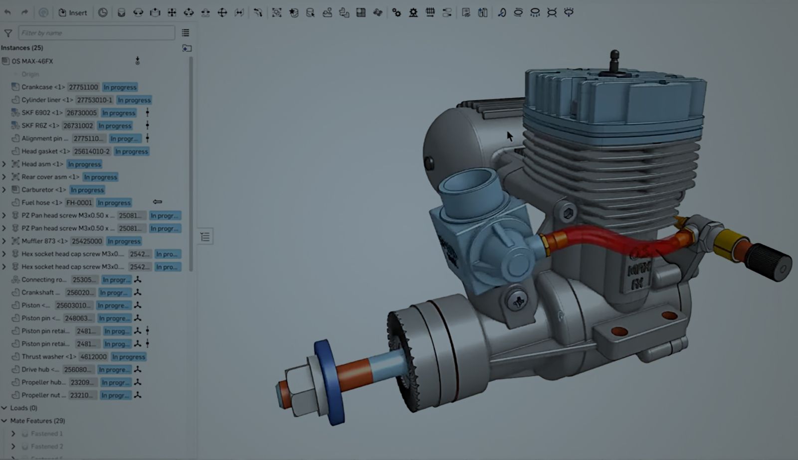
4. Nitro Engine
The nitro engine example demonstrated how multi-part part studios can streamline complex assemblies by using skeleton sketches and layout sketches. Brown showed how dividing the model into core features (such as the engine block and exhaust) allowed for more efficient modeling. Parts that wouldn’t change frequently, like the bearings, were organized separately, while the machining features were given specific colors to distinguish them from other components.
This method ensured the design intent remained clear and allowed for easy modification of critical components without affecting the entire model.
Greg Brown
This is an old, an engine for a radio controlled car.
And the real question about this is multi part Part Studio versus assembly versus lots of part parts, lots of part studios.
And let's try to address some of that, right up front here so you can see actually it's got a lot of nice parts on it. If I cut the cross section through here. So clearly this needs to be an assembly.
But the first sort of chicken or egg question that might get asked is well, how much do you put in a single part studio versus separate part studios? And the answer of course is, it depends, and it depends on your intent.
You could do a lot of these things in a single part studio, because this is not a crazy number of features or crazy number of difficulty of topology. But what I have done, is one way to approach it here, and that is to isolate a key component, which is the crankcase, and then have a look at the things that are directly touching it, and sort of the functional areas of it.
And what I've done is I actually modeled these things in three real big stages. The core features, the casting features, and then the machining features, which is exactly how you would think about design for manufacture, right, and the design for assembly, and the functional design of this thing to start with.
So when I say core, I'm going to isolate them and show you that I created these features as solids. First, they're not actually, they're multi parts in here. One of them represents the exhaust port, one of them represents the cylinder and the ports around the cylinder, and one of them represents the intake and everything that's going to go on the inside.
So I can allocate variables to these. And you can see here, I've used a variable studio for top level, document-wide variables, as well as variables that are specific and local to the crankcase itself.
So, variables, and variable studios are a key part of this getting organized theme. And those variables are driving these core things. Now, there's a number of other ones that are important too, and that is where you have bought in components.
So there's an r six z bearing that goes in the front here, the sealed bearing, and then there's a 6902 bearing inside of here. these are things that I don't need to model as part of this part studio, because they're an established standard, so that the outer diameters of those, are going to be core.
So that is one way that I can sort of say I'm going to draw the line as to how much I model inside a single part studio.
the way that I've done this then, is that after I've created these core features, and you can see again, it creates multiple parts in here, I'm actually not going to ever ship these parts or manufacture these parts.
These are purely for sort of functional development. But later on you'll see that there's a big boolean feature, which is where I subtract those core parts away from what I had been creating, which is the casting, this investment casting or whatever the casting process is going to be, for this.
So I don't ever throw these tools away. This is also a little bit of a tip, because it makes for some nice eye candy for looking at later on.
But it also helps me doing measurements and all sorts of other things like that. So keeping these tools in here, whereas the part that I'm actually going to put in the assembly, is this one here.
Final word on this, other than you can see that I've named things and I've kept things nicely arranged in folders, is that anything that's going to be touched by a machine, is red.
So I've created those colors. And there's actually a really nice way to do that. you just right click on a feature and say, "add appearance to feature". And that's a nice little tip, to keep things, organized in that way.
Now, you can choose whatever color, of course, that you decide makes sense for you.
5. Cylinder Head
In the cylinder head case study, Greg illustrated how parametric modeling can be used to manage the coolant channels, combustion chambers, and intricate valve geometry in a highly complex part.
By organizing the design using layout sketches, the team was able to control key dimensions such as valve offsets and bore diameters. Colors and variables were applied to distinguish between intake and exhaust systems, which improved clarity and allowed for rapid adjustments.
This modular, top-down approach ensured that changes to the cooling system or cylinder layout didn’t disrupt the entire design.
Greg Brown
The next one, is a cylinder head. This is a pretty complicated one because there's a lot of variables, and there's a lot of design for dot dot dot kind of considerations that need to be made from both the casting, the manufacturing, the functional.
And you might actually, as I suggest down here, want to be doing some simulation, along the way, sort of using design,-led simulation or simulation-based design.
So let's delve into this one because it's a pretty fun model to have a look at. So just to show you, this is an outcome. If I cut through it, you'll see that it's pretty complicated on the inside, and there's obviously a repeating unit, which I'll make very good use of.
And of course, this isn't the final cylinder head. This is in the conceptual stage or the model building stage, which I wanted to show you because this is the really key part, and this is where you get the benefit, if you can think up front, rather than just think of the final, shape, if you try to think of the final shape and then just model all these fillets one by one by one, this is going to be a little bit of a nightmare.
So let's break it down into the constitutive, the parts here. So this is the repeating unit of the combustion chamber, the valves, the inlet and outlet ports.
And the way that I've done this is similar to what Cody's talked about before is with a lot of very important layout sketches. Now, these sketches, which have been defined up here in the layout section, contain the very core things like the bore diameters, the valve offsets and angles.
And you can see all those are related to variables again, as well. Some of these are calculated with expressions, ratios here and there. And actually, I build a lot of these calculations into the variables with expressions just to make sure, as a little bit of a design check as I go along, make sure that the volume of the cylinder, the combustion chamber, is not getting beyond a certain limit.
I have those expressions built into here, and so that I can keep a check on that with respect to these sketches in here, these layout sketches, you can see that I've used colors.
Hopefully they show up well for everybody. And I've used colors that are appropriate for my eyes. And you can see that on the intake side, everything's green. You can see here, this is the, if I highlight there, you can see this is the intake port spline that I'm using to show the shape of that.
So, not only I've named it nicely, but I've also colored it. I know that everything green is on the intake side. Everything on red is on the exhaust side. It's impossible to keep track of so many complicated sketches, unless you use some very, very rigid and diligent scheme, for these kinds of things.
And in the end, I've created a bunch of, parts in this multi-part Part Studio. You can see here, I've created the combustion chamber, the inlet ports.
there's some clearance for the spark plug. And then the really difficult part is the blue stuff, which is where the coolant is going to go. And the coolant is offset from a lot of these things.
And you can see how it makes sense to do things very, very closely topologically related. That is one way to do it. The other way to do it is to take a multi-part studio approach where you end up with ultimately the same end result.
Actually what was really interesting is if I have a look at the regeneration times, about 8 seconds for this, and there's 300 features. So it's a decent sized part studio, well within our guidelines for what you should expect for performance.
In this case, if I have a look at this part studio, which is the final slice, you'll notice that it's really fast, it's just over a second. And the reason for that is that I have used version references and derived things in.
I've derived stuff like those cores for the ports and the cores for the combustion chamber. I've derived them into this part studio and then done my booleans at that stage here.
So again, this is the intent and question mark. And it depends is always the answer to that. And the reason I did it this way is that I'm making a lot of changes that are going to be potentially for just at this local level.
And I don't need to regenerate everything that went into the combustion chamber. All these complicated ports and lofts that are in there. I don't want to regenerate that every time. I just want to regenerate the bits that are here.
Perhaps I'm doing some simulation and I'm looking at just these particular fillets. So splitting things up, there's no right or wrong way. Well, there's wrong ways, but there's not good ways.
But in this case, whether I do it in a single part studio with lots of carefully controlled references or multiple part studios, where in this first part studio you can see I just had a few datum planes, a few of these sketches and a couple of keepout zones.
And that constitutes all of the layout, which is going to go into these other steps.
6. Chair
The Bauhaus chair case study highlighted the use of layout sketches and routing curves. By leveraging parametric expressions to control bend radii and frame dimensions, Brown showed how the chair could be dynamically resized while ensuring that all components fit together perfectly.
This approach underscored the importance of a resilient design that can respond to user-defined changes without manual rework.
Greg Brown
So some of you may have recognized this chair. It's a pretty common or famous one from the Bauhaus, almost exactly 100 years old, I think this design. This is a very good example to use skeletons to drive the shapes, and expressions.
And something else I'll bring in here, which is a measured variable. So let's go back to this and have a quick look. So the assembly of this chair is nice.
And if I just show you a couple of things that introduce complexity, is that there's a lot of offsets that are simple.
And then you think about them and say, oh, actually, they're not so simple after all. And you want to get these things right so that the holes line up. Sorry, I just overshot there a little bit.
You want to line these up so that in response to change, whether that change is intended because you're going to release a family of things or you just want to have a resilient, robust model, which is always a good idea anyway.
They're not as simple as they look. So let's have a look at the part studio, that created this. And I'm going to draw your attention to the purple big blob and the sketch.
These red sketches, hopefully they show up for you as well. So these really define the overwhelmingly driving dimensions for this chair. You'll see at height, width, depth, and the front depth for the cutout and the rear depth for a cutout.
These are the things that probably appear on the specification sheet if you go to the catalog. These are the things that I'm definitely going to assign variables to. And I can flex this thing obviously in milliseconds to create.
It's a very, very simple model. But simple is good in this case because I can make it overly complicated too soon. That's a trap. You want to keep things clean, you want to keep things simple, so that they respond resiliently to change.
So the way that this then worked, this part studio, you see, I haven't modeled all of the parts because that's in the assembly. You'll see down here, if I turn off the parts and turn off the composite parts here that I created, these blue routing curves.
And the blue routing curve is actually using a new custom feature we've created called routing curve. And this is a very convenient way to define the path for the frames that are going to come in here.
So you can see here we've got a routing curve. The routing curve is then now going to reference the vertices of those sketches, those driving sketches.
And, that is, that's the key to it. The bend radii in the routing curve, they are being referred to variables. So it's all, it's following all of these guidelines.
Use expressions, use variables, use colors. the blue things are always the routing curves in my own definition. And then from that, then you can create the, frame feature, which is something that's a very strong, powerful tool set in Onshape I can just use that single routing curve, to create the back frame, a single frame feature to create the base frame, and one more to do the seat frame.
That is really a really efficient way to make this thing, resilient to changes as well. So even though I'm going to hide this now. Even though this chair only comes in one frame size, which is three quarter inch, I've actually created a configuration so that I can update this configuration.
And you'll notice that all of the, they fit together perfectly, right. It always fits together perfectly. Everything updates resiliently and you can see why, I think it was, Marcel Breuer, he didn't design this thing with one and a half inch, tubes. He designed it with three quarter inch tubes. But having it with the ability to make these changes really rapidly is always a very good thing.
7. Glider
The Aries glider project pushed parametric design to its limits with a highly detailed, hyperparametric model of an aircraft wing. By using layout sketches, expressions, and variable-driven patterns, the model could handle complex relationships between the wing’s sweep angle, dihedral, and rib spacing. For example, increasing the wing span automatically adjusted the spacing of the ribs and updated the geometry of the leading and trailing edges.
This example showcased how hyperparametric techniques can create incredibly robust models that adapt dynamically to design changes, ensuring precise control over every aspect of the structure.
Greg Brown
This is one of my favorite models here, which exhibits what I, and what Cody and we were talking about before, which is "hyper"-parametric modeling, which, is, as a bit of a fun title, I don't think there's an official scientific definition for that, but it's one way to describe it is making things overly parametric, even if you didn't need to.
Right. And in this case, I don't need to create multiple configurations like that pipe flange. I'm actually just releasing a single design of this.
But what if I could make this so resilient to change the swept back angle or the dihedral or the washout or the thickness of all of these, in all of these members in here.
And if I take a cross section through here, you'll see that this is very, very detailed modeling in here. And everything does fit perfectly. All of these mitres are perfect.
And all of these components, if I just highlight that, you can see how the cutouts on the front, the leading edge and the trailing edge, everything was done perfectly.
There's nothing left. Oh, well, whoever's putting it together can just adjust to taste or to adjust. This was an exercise in how parametric and how robust can we make this thing.
And one of the really key aspects to doing this is creating patterns of features or patterns of parts that, respond very well to outside influences.
So, the outside influence for this, again, would be variables. And the variables being the sweep back angle or the cord length at the root versus the cord length at the tip.
And of course, if I start changing those things, then all of the ribs and all of these intermediate diagonal ribs will also have to change. That is, the key challenge for this in here.
And actually it's worth noting, for a second here about document structure as well. Here I've got a single document, which has a number of things in it. Part studios, drawings, some reference images, some renderings that I was doing here before. And I'm modeling the fuselage in this document as well.
The wing is actually coming from a second document. You can see here that, it's actually showing you that it's linked in from a different document. And that is a very good, option to have at your fingertips, different groups working on different things.
Maybe there's a different release scheme or release, strategy that you're going to have with components which or subassemblies, which have a different sort of cadence to them.
So here in this fuselage, I can focus on creating, getting the electronics right, getting the wiring right, and all of those things.
Whereas, the wing document takes care of itself. And then I can incorporate it, when and where and update the versions as things change. You can see here, actually, there's a new version of that wing available that, I could update.
Quick note here on colors, decals. Also a very important thing. You see how much realism. It adds a level to it now. Even if it's not just putting a manufacturer logo onto it or some other person's logo onto it.
So it's a really good idea to use colors and even decals to remind you of certain things. Like this is the intake side or this is up. Or, you can do all of those sorts of things even as temporary measures, just so that you can manage your complexity in here, just so that it's absolutely clear and you don't end up putting something on the wrong side of where it should have been put to start with.
8. Fretboard
The fretboard example demonstrated advanced patterning techniques in Onshape, focusing on the unique design of fan frets found on certain guitars. The number and angle of frets adjusted automatically based on string length and configuration inputs, allowing for a completely customizable design.
This was achieved using expressions and feature patterns, creating a fretboard that could handle a wide range of configurations while maintaining perfect alignment across the entire model. This approach highlights how Onshape’s patterning capabilities can be used for highly specific, custom designs.
Greg Brown
And this shows an interesting use of patterning in Onshape, which is one of the hidden superpowers. So in this particular guitar. And if those of you have sort of heavy metal fans might recognize the frets on this guitar board aren't straight or sort of perpendicular across.
There's a very interesting pattern and they're called a fan pattern, right, or the fan frets here. So being able to capture the intent of this is a really, really key, powerful thing we can do.
So, just like Cody showed before, I've got a number of inputs to my configuration, the number of frets, the length of the strings, which will affect sound.
Of course, there's a lot of expressions in here to determine angles, and then there's this really, really interesting pattern. And I'm not going to get enough time to explain fully into this, but you can see here I'm doing a feature pattern, and these are all of the features that are participating in the pattern.
And obviously there's things being driven by variables from the outside and really, really important button here, which is to reapply features, which is recalculate the topology as we go down this pattern.
Now in computer language, this is essentially the same as doing a for-loop, where I've got I equals zero to sum to 22 or one to 22, and I'm doing my calculations over and over again inside of a for-loop.
And it's just a lot more friendly, though, to be able to do this graphically in the way that we do it in Onshape. so I put that out there without further explanation and something that's worth deep diving into at a time in future to explore how these advanced patternings can really take care of a lot of the automation, and capture your design intent.
Parametric 3D CAD, Plus More
Mastering design intent and managing complexity are critical for building flexible, resilient models that can adapt to any project's demands.
With Onshape’s advanced tools – like parametric modeling, multi-part part studios, and configurations – you can streamline your workflows and make smarter, more adaptable designs. If you’re ready to take your design process to the next level and unlock the full potential of these powerful features, sign up for Onshape Professional and experience firsthand how it can transform the way you work.