
1:19
When you convert sheet metal components from legacy systems you often need different sheet metal bend geometry. Onshape uses a unique approach to bent and flattened states of a component that allows you to modify the design in both states.
Modeling Using Standard Features
If you want a sheet metal component, you can use standard modeling practices to create the geometry and then use Onshape’s Sheet Metal model feature to convert the model to sheet metal.
Once the model is converted, the bends and corners may not meet your specifications, or you may be using the Sheet Metal tools in Onshape to mimic other bending applications like flexible printed circuits or paperboard boxes.
Modifying the 3D and Flat Pattern
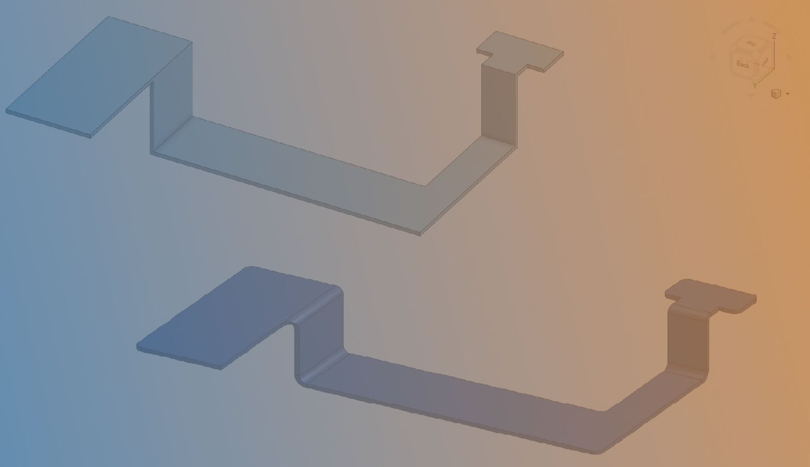
In the following example, we have a sheet metal model that requires bend and corner alterations. Using the power of Onshape's features, these modifications are easily made in just a few steps.
1. Modify the converted part with the Move Face feature. This removes unwanted material.
2. The Move Face feature also allows you to add extra material.
3. Modify the model to have the specified geometry in the Flat View.
4. The 3D model updates at the same time.
This Tech Tip helped you learn how to modify Sheet Metal models to achieve the desired geometry. Watch the video below to see this tip in action.
For more information on removing holes in sheet metal models, see our Tech Tip on how to easily remove holes in sheet metal parts. In addition, check out the Tech Tip on Partial Flanges.
The Onshape Learning Center
Take self-paced courses, read articles, or sign up for an instructor-led training session.
最新コンテンツ
- ブログ
- Becoming an Expert
- アセンブリ
Built to Scale: Why Large Assemblies Don’t Slow Down in Onshape
07.16.2026 もっと見る- ブログ
- News from Onshape @ PTC
- Artificial Intelligence
Onshape Labs: AI in CAD Guided by Designers, Driven by Innovation
07.15.2026 もっと見る- ブログ
- Evaluating Onshape
- データ管理
- 共同作業
- Artificial Intelligence
How the Most Underrated CAD Feature Improves Design Workflows
07.09.2026 もっと見る