
05:56
Realizing your full design means building your assemblies to capture motion, interface, and fit.
All CAD tools offer some mechanism for creating assemblies from the parts you design, but Onshape handles the process of assembling these components in a different, faster way.
Mates: Building Assembly Relationships
Assembling components in any design tool means establishing relationships between components, whether these are called Mates, Assembly Constraints, Joints, etc.
In most 3D design tools, you create these assembly relationships by removing 1 or 2 degrees of freedom at a time until the components are eventually fully restrained or only allow for the desired motion. In most cases, the software typically requires three mates to fully define the location of a component in an assembly.
In Onshape, Mates work differently than in other design tools. Instead of removing one or two constraints at a time, the base mate Fasten removes all 6 degrees of freedom in one operation. There are additional mates in Onshape that allow for more flexibility by enabling movement in a variety of degrees of freedom (more on that below).
Unlike most design software that require separate assembly relations to define angles and distances, Onshape integrates these values directly into all of its mates while also providing limits for linear and rotational values.
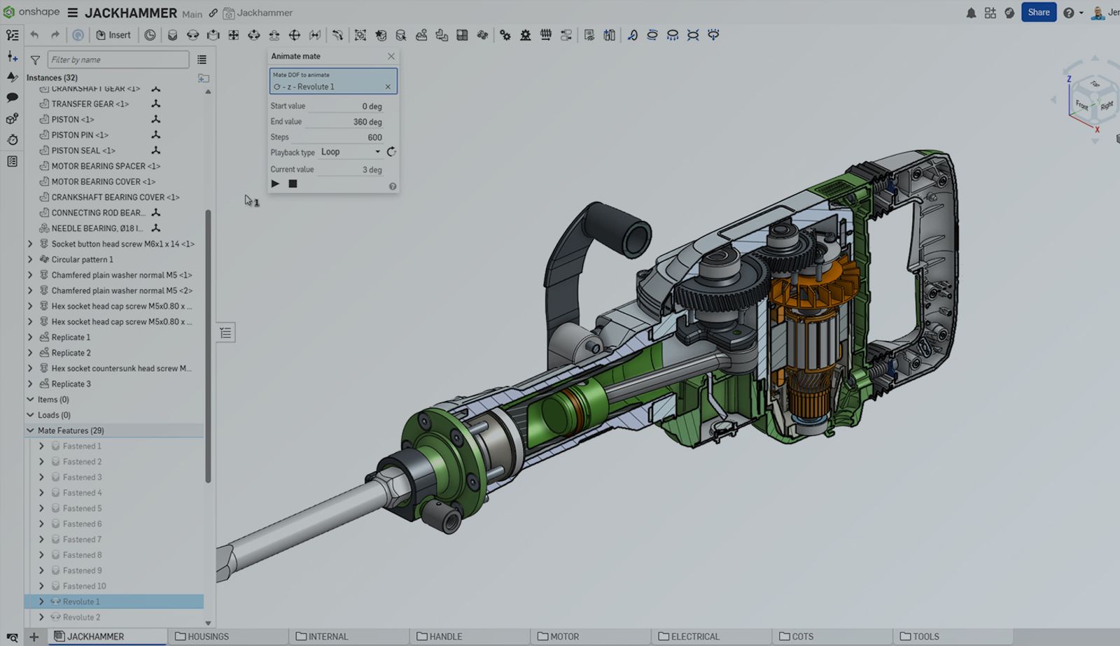
All of this ultimately means that you create far fewer mates in Onshape. This saves time in the creation of the mates, less mates to manage, and fewer mates to calculate. For example, in the image below, only 29 Mate Features are used to fully define the relationships between 32 top-level parts and assemblies.
Mate Connectors
One of the unique aspects of assembling components in Onshape is the use of Mate Connectors. Instead of selecting a surface, plane, or a point on one of the components to mate, you select one of many “points” that appear on any surface you hover over. These aren’t just the vertices of the surface. Instead, each of these points defines a Mate Connector that can be modified by allowing for an offset in any direction or rotation about an angle.
These Mate Connectors also appear over key points of geometry, such as the axis of a cylindrical surface, the center of all selected geometry, etc. Each Mate Connector has a primary Z Axis as well as an X and Y Axis. These are used along with mates to define the relationships between two components.
Types of Onshape Mates
Once the two Mate Connectors are selected, you can establish a relationship between the two components and their respective Mate Connectors.
Let’s take a deeper look at each of the mate types in Onshape to better understand how each mate defines degrees of freedom in an assembly. Each mate type is created between two components to establish how they move between one another.
Fastened
The Fastened mate is the most defining and most commonly used mate in Onshape. It removes all degrees of freedom from a component in a single mate. Within this Mate, you can control offsets or distances in X, Y, and Z as well as define rotation about either X, Y, or Z.
Revolute
The Revolute mate removes all degrees of freedom except for rotation along the Z axis defined by the selected Mate Connectors.
Slider
The Slider mate removes all degrees of freedom except for translational movement along the Z axis defined by the selected Mate Connectors.
Cylindrical
The Cylindrical mate is a combination of the Revolute and Slider mates in that it allows rotational movement and translational movement along the Z axis defined by the selected Mate Connectors.
Pin Slot
The Pin Slot mate allows rotation about the Z axis and also translational motion along the X axis of the selected Mate Connectors.
Planar
The Planar mate removes all degrees of freedom except for linear, or translational movement along the X and Y axes of the selected Mate Connectors. This is most similar to a Coincident, Flush, or Simple relationship in other 3D design software.
This mate should not be used like it is in traditional 3D design tools. Instead of using 3 Planar mates, you should always look to use one of the previous mates first, and instead use Planar to finalize the motion defined by mates such as Revolute, Slider, Cylindrical, etc.
Ball
The Ball mate allows rotational movement along all three axes, but does not allow any translational movement between the selected Mate Connectors. This would be most similar to mating 2 points together in a traditional design tool.
Parallel
The Parallel mate allows rotational motion along the shared Z axis of the selected Mate Connectors, and translation motion in any of the three axes shared between Mate Connectors.
Tangent
The Tangent mate in Onshape is different from any of the other mates in that it does not use Mate Connectors to define the relationship between two components. Instead, you select two surfaces, and tangency is maintained between them.
Types of Mate Relations
Finally, you can add mechanical motion between two mates using Relations in Onshape. These add more complex, often ratio-driven relationships between two already established Mates. These are the four different Relationships you can create in Onshape.
Gear
The Gear relationship creates a ratio of rotational motion between two Mates with rotational degrees of freedom (e.g., Revolute, Cylindrical). Think of this like the relationship between two gears or pulleys.
Rack and Pinion
The Rack and Pinion relationship creates a ratio between the rotational motion of one mate and the linear motion of the other. Think of this as the linear motion of a rack in relation to the rotary motion of a pinion gear, hence the name.
Screw
The Screw relationship is similar to the Rack and Pinion relationship, except you only select a single Cylindrical mate. You define the ratio between the rotational degree of freedom to the translational degree of freedom in the same Cylindrical mate. This way, as the component is rotated, it also moves in the linear direction, or vice versa.
Linear
The Linear relationship establishes a relationship between the linear motion of two mates that allows for translational motion. You can establish a ratio between the motion of these components and define the direction in which each moves relative to the other. For example, a telescoping cylinder may have one component move twice the distance of another component it's related to.
Bringing It All Together
Using the mates and relationships in Onshape, you have all of the tools you need to rapidly establish the relationships and motion between components in an assembly.
You can watch the video below to see just how easy it is to fully assemble the 32 top-level parts and assemblies in the Jackhammer shown in the images above with just 29 Mates and Relations.
Interested in learning more about building assemblies in Onshape? You can take this Introduction to Assemblies course in the Onshape Learning Center.
Want to build your assemblies and see how many fewer mates you can build your own designs? Sign up for the Onshape Discovery Program today and start creating and assembling your own models.
The Onshape Discovery Program
Learn how qualified CAD professionals can get Onshape Professional for up to 6 months – at no cost!
Latest Content
- Blog
- Becoming an Expert
- Assemblies
Built to Scale: Why Large Assemblies Don’t Slow Down in Onshape
07.16.2026 learn more- Blog
- News from Onshape @ PTC
- Artificial Intelligence
Onshape Labs: AI in CAD Guided by Designers, Driven by Innovation
07.15.2026 learn more- Blog
- Evaluating Onshape
- Data Management
- Collaboration
- Artificial Intelligence
How the Most Underrated CAD Feature Improves Design Workflows
07.09.2026 learn more