
00:00
Traditional CAD constrains degrees of freedom to simulate physical connections, i.e., Coincident, Concentric, Parallel, etc.
For example, a "Concentric" mate combined with a "Coincident" mate creates a hinge joint. This architecture generally forces motion analysis to be a distinct, post-modeling validation step rather than a real-time, interactive process, limiting immediate feedback on mechanism behavior during the design phase.
Onshape Assemblies begin with higher-level Mates, for more integrated motion analysis.
This blog will walk you through the philosophy of Onshape mates, how to define complex kinematics such as gear relations, and how to leverage these connections for structural simulation.
High-Level Mates vs. Low-Level Constraints
Traditional CAD often requires three separate constraints to lock a part in place, for example, a bolt into a hole: a concentric mate for the shaft, a coincident mate for the head, and a parallel mate to stop rotation.
In Onshape, this is handled by a single Fastened Mate.
Onshape Mates are based on Mate Connectors – local coordinate systems attached to parts. When you mate two parts, you are simply aligning two coordinate systems. The type of mate you choose dictates which degrees of freedom (translation and rotation along X, Y, and Z) remain free.
Onshape offers two types of mate connectors:
- Implicit Connectors: When you hover over a face or edge while the Mate tool is active, Onshape suggests points (center of a circle, midpoint of a line, corner of a cube). These are implicit connectors.
- Explicit Connectors: You can manually place a Mate Connector on a part in a Part Studio. This is useful when picking the connection points is a more involved process.
The Library of Motion: Mate Types Explained
Choosing the right mate is about asking: How should this part move relative to the other?
Some basic mates below:
- Fastened Mate: Removes all 6 degrees of freedom. The parts are completely bonded.
- Parallel Mate: Allows translation in X, Y, and Z, and rotation around the Z-axis, but prevents tilting. It keeps axes parallel.
- Slider Mate: Allows translation along the Z-axis only. Perfect for hydraulic pistons or linear rails.
- Revolute Mate: Allows rotation around the Z-axis only. Used for hinges, wheels, and pivots.
- Cylindrical Mate: A combination of Slider and Revolute. The part can rotate around and slide along the Z-axis. Think of a bolt being threaded (before it tightens) or a shock absorber shaft.
- Pin Slot Mate: Allows rotation around Z and translation along X. This is specific to tracking mechanisms where a pin follows a linear path but can freely rotate.
- Planar Mate: Allows translation in X and Y, and rotation around Z. The part slides on a flat surface (like a hockey puck).
- Ball Mate: Allows rotation around all three axes (X, Y, Z) but prevents translation. Used for ball-and-socket joints.
Defining Limits and Range of Motion
Mates don't just define how things move; they define where motion begins and stops. In Onshape, limits are built directly into the Mate dialog. When you edit a Revolute or Slider mate, check the Limits box and define the hard stops for the range of motion.
Advanced Kinematics: Gears and Relations
Mates define the motion of a single pair of parts. Relations couple the motion of multiple mates together. This is how you build transmissions, steering racks, and linkages.
Gear Relation: This links two rotational mates (Revolute or Cylindrical).
- Select the Gear Relation tool.
- Click the two existing mates (e.g., Revolute 1 on the pinion and Revolute 2 on the spur gear).
- Set the Ratio. You can define this by teeth count (e.g., 20:40 is equal to a ratio of 0.5). Note: This does not detect geometry collisions; it is a mathematical link. If your gears are visually intersecting, use the "Animate" tool to check, but the relation will drive them regardless.
Rack and Pinion relations, Screw relations, and linear relations are also available. The only difference is the degrees of freedom that are paired.
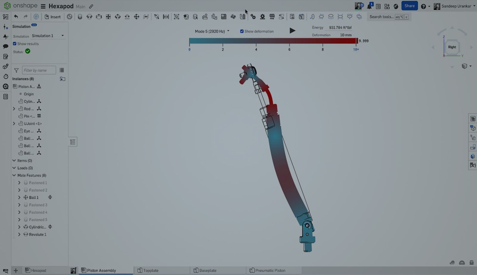
Simulation Connections: Mates in FEA
One of Onshape’s most powerful additions is CAD-integrated Simulation for linear static stress and modal analysis. A common misconception is that simulation requires a completely different setup than the kinematic assembly. In Onshape, your Mates are your Simulation connections. Just specify the simulation connection while defining the mate!
The Onshape Discovery Program
Learn how qualified CAD professionals can get Onshape Professional for up to 6 months – at no cost!
Latest Content
- Case Study
- Consumer Products
How Spin Master Achieved 5X Faster Design and 20X Faster Collaboration by Eliminating CAD Friction
06.01.2026 learn more- Blog
- News from Onshape @ PTC
- Artificial Intelligence
Onshape Labs: AI in CAD Guided by Designers, Driven by Innovation
07.15.2026 learn more- Blog
- Evaluating Onshape
- Data Management
- Collaboration
- Artificial Intelligence
How the Most Underrated CAD Feature Improves Design Workflows
07.09.2026 learn more- Blog
- Evaluating Onshape
- Collaboration
With Cloud CAD and PDM, Flexible Design for a Summer Coolcation
07.02.2026 learn more