
05:13
Efficient Onshape assembly navigation requires clear visualization. While manual component hiding/showing is one option, it can be slow when trying to work on a large assembly with many instances.
While this Tech Tip covers the Isolate and Make transparent commands, which streamline workflow and improve interaction/analysis of Onshape assemblies, these two commands are also available in Parts Studios.
Isolate and Make Transparent
The Isolate command keeps all selected assembly entities opaque while making other entities transparent. Make transparent is the reverse process, making selected components see-through while leaving all others opaque.
Both these tools are invaluable when you need to understand the relationship between internal and external components without having to remove instances from view. Your workspace is decluttered, and you can focus on specific components in a dense assembly. These commands are crucial for detailed inspection and precise interaction.
How It Works
- From the instances list or the graphics area, select one or more instances you want to isolate or make transparent.
- Right-click and select Isolate or Make transparent from the context menu.
Keyboard Shortcuts
For rapid application, select your instance(s) and press Shift+i (Isolate) or Shift+t (Make transparent). To add more parts to your isolated or transparent view, select them and press Shift+i/Shift+t again.
You can also use the Select other (`) key (grave accent key, to the left of the “1” key) to select additional entities cumulatively.
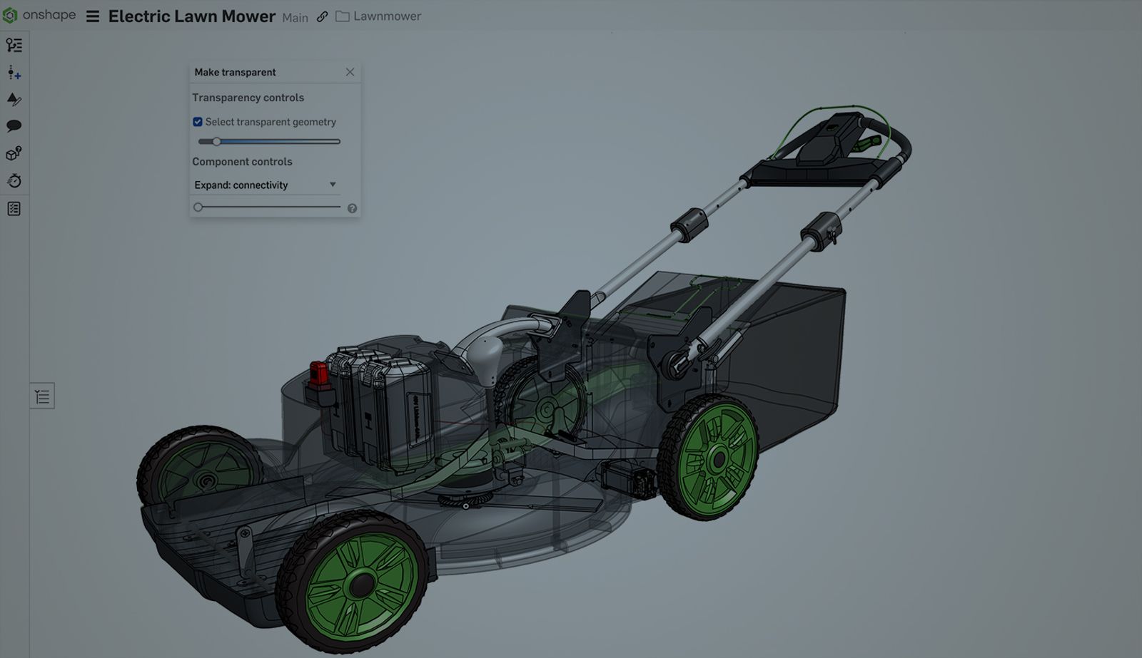
Transparency Controls
Isolate and Make transparent commands offer more than just hiding or showing components; they are used for focused interaction within a given context. A Transparency slider control appears, allowing you to fine-tune the transparency of the selected (if make transparent is used) or non-selected (if isolated is used) geometry, as well as the model’s internal geometry. This balance of focus and context is crucial for understanding how your isolated parts integrate into the larger assembly.
If you set the slider to the far left, only the outer edges of the transparent geometry are displayed. The internal geometry of the selection is not displayed. If you set the slider to the far right, the selected transparent geometry is made completely invisible. Any slider setting other than left or right adjusts the transparency of the model’s internal geometry from very opaque (at left) to very faint (at right).
Component Controls: Expanding Isolated or Transparent Instances
Additional Component controls offer powerful ways to expand your selection beyond the instances you originally selected:
- Expand: connectivity: Use a slider to successively include more instances based on their mate connections to your initial selection. This is invaluable for tracing assembly chains.
- Expand: distance: Use a slider to successively include more instances based on their physical proximity to your selected part(s). This is useful for isolating regions of your assembly.
Check Select transparent geometry to temporarily interact with the internal geometry of the model without exiting Isolate or Make Transparent mode. While this option is checked, you can select, measure, analyze, and edit the instances, points, edges, faces, mate connectors, and groups in the graphics area.
Exiting Isolate or Make Transparent Mode
To exit Isolate or Make transparent mode, click “x” in the upper right corner of the dialog, or press the Esc (Escape) key. Alternatively, right-click anywhere in the graphics area and select Exit isolate/Exit make transparent, or press the Esc key for a quick return to your full assembly view.
The Select transparent geometry and Transparency slider settings are remembered if you exit the dialog and re-enter. These settings are not remembered between sessions (if you refresh the browser or exit the document tab).
Isolate Applications
- Quick Inspection: Instantly zoom in on internal features.
- Mating Operations: Simplifies the process of creating and adjusting mates by minimizing visual distractions.
- Troubleshooting: See interferences or alignment issues.
Make Transparent Applications
- Internal Visibility: Peek inside enclosures to understand component layout.
- Clearance Checks: Visualize space and potential clashes.
- Contextual Understanding: Maintain a sense of the whole assembly while inspecting hidden parts.
The Power of Both: Complementary Visibility Tools
While Isolate and Make transparent are distinct commands, they become incredibly powerful when used strategically to enhance your assembly views. They function as complementary tools, allowing you to tailor your visualization for specific tasks.
You might first use Make transparent on outer components (like a casing) to visually expose the inner parts. This helps you identify the specific internal subassembly you want to examine. Once identified, select that part or assembly. Then press Esc to return to the full assembly. You can then Isolate (press Shit + I) that internal sub-assembly. When you isolate, the outer parts (and any other parts not explicitly selected for isolation) are made transparent based on the Isolate command’s background setting, providing vital context around your sharply focused, isolated components.
Additionally, remember that both Isolate and Make transparent can be applied not just to individual instances, but also to groups or folders within your assembly Instances list. This means you can efficiently manage the visibility state for an entire subassembly or logical grouping of parts with a single command. By selecting a folder and applying Isolate or Make transparent, you instantly control the visibility of all components contained within that folder, dramatically speeding up your workflow when dealing with highly complex assemblies.
By using Isolate and Make transparent, along with their associated shortcut keys (Shift+, Esc, and Shift+t), and leveraging advanced controls like the transparency slider, Select transparent geometry, and efficient component control via folders, you navigate and manage your Onshape assemblies with enhanced speed and efficiency. Give them a try in your next design session.
For more detailed information, check out the Onshape Help Documentation:
Onshape on YouTube
Subscribe to our channel to stay up-to-date on new product releases, Onshape Tech Tips, and more!
Latest Content
- Blog
- Evaluating Onshape
- Arena PLM Connection
The Cloud-Native CAD-PDM-PLM Workflow That Finds Problems Before They Cost You
06.11.2026 learn more- Blog
- News from Onshape @ PTC
- Artificial Intelligence
- Robotics
How Multi-Agent Orchestration Between Onshape and NVIDIA Improves CAD-to-Simulation Workflows
06.01.2026 learn more- Blog
- Evaluating Onshape
- Robotics
- Aviation, Aerospace & Defense
- Collaboration
- Integrations
- Arena PLM Connection
- Data Management
Why the Best Hardware Teams Have Started Talking Like Software Engineers
05.28.2026 learn more