
00:00
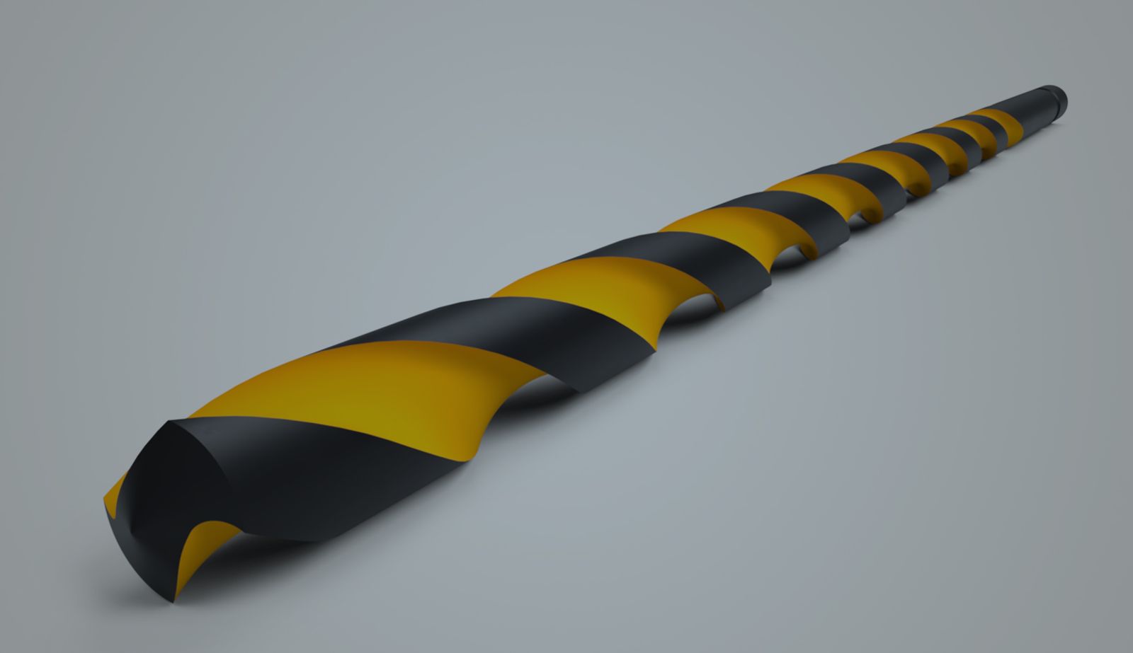
There are many great videos on how to create a drill bit with a Helix curve. In this Tech Tip, let’s add a twist by not using the curve.
The Wrap feature is typically used to create raised or engraved text or geometries. However, it can also be used to create the flute, with one additional benefit, that is, to control the helix angle in a more intuitive way.
Let’s review how a flute is normally created using a Helix curve.
After creating the body, start the Helix curve using either a cylindrical face or a circular edge. An important parameter in drill bit design is the “Helix angle”, which is the angle measured between the helical line and the axis.
From the Helix feature dialog, there is no input for the Helix angle. It can still relate it to the pitch with an expression, where pitch = tan( 90 deg - helix angle) x π × diameter.
Using the Wrap feature, the helix angle can be input and configured straightforwardly. Below are two ways to define it.
Using the Wrap Feature: Method 1
First, create a rectangle in a sketch, at a 90-degree angle to the drill bit body. Click the Wrap feature tool. In the Surface tab, choose the sketch region as the Tool and the cylindrical face as the Target. Use the corner of the rectangle as the Tool’s anchor point, then the center of the round face as the Target anchor point, making sure the Z-axis points upward and the mate connector origin is slightly off-center. Expand the Position caret and observe how increasing the angle affects the ribbon.
Verify that the path length is the same. Then, input 90 deg - Helix angle into the Angle field of the Wrap dialog, since it is the complementary angle of the helix angle. Now, the effect of the Helix angle is visible from the Configurable variable.
Verify the edge of the Wrap feature with the Helix curve created earlier. Next, create the flute by using Sweep tool to remove the excess material defined in the Flute Profile sketch as you normally do, while choosing the Lock profile face option.
Using the Wrap Feature: Method 2
In the second method, place the ribbon sketch at an angle to the rod. Remember to use the variable to control this angular dimension. In this case, the Wrap angle has to be 0.
For the flute termination, use Move face and Delete face for the final touch.
Lastly, circular pattern this flute to the other side, then create the drill point with the Revolve tool to remove the material as defined in the sketch region.
This Tech Tip helped you explore Onshape’s advanced part design capabilities and how you can easily create a drill bit by using alternate methods with considerations of important parameters. Watch the video below for more:
For additional learning materials, explore our training courses and videos on using curves and advanced part design in Understanding Curves and Advanced Part Design.
Friends Don’t Let Friends Use Old CAD!
Know a colleague who could benefit from our cloud-native, fully-featured collaborative design platform?
Latest Content
- Blog
- News from Onshape @ PTC
- Artificial Intelligence
- Robotics
How Multi-Agent Orchestration Between Onshape and NVIDIA Improves CAD-to-Simulation Workflows
06.01.2026 learn more- Blog
- Evaluating Onshape
- Robotics
- Aviation, Aerospace & Defense
- Collaboration
- Integrations
- Arena PLM Connection
- Data Management
Why the Best Hardware Teams Have Started Talking Like Software Engineers
05.28.2026 learn more- Blog
- News from Onshape @ PTC
- Collaboration
Why Curiosity Builds Emotional Intelligence and Improves Engineering Workflows
05.27.2026 learn more