
00:00
What’s the Purpose of Construction Lines?
Construction lines serve as non-geometry references that define structural intent without contributing to actual model geometry. This separation between reference and model geometry is fundamental to parametric CAD design, allowing you to build fully defined, easily modifiable models where design intent is captured through relationships rather than static geometry.
Construction Lines in Sketches
When sketching, construction lines can serve various purposes: references for constraints and dimensions, axes for downstream features, and more.
Construction lines are useful for almost all sketch constraints, from mirroring or symmetry inside a sketch, to tangent relationships for arcs and splines, to general references like parallel or coincident. In these cases, construction lines provide sketch references that fully define the sketch contours and are used in downstream features.
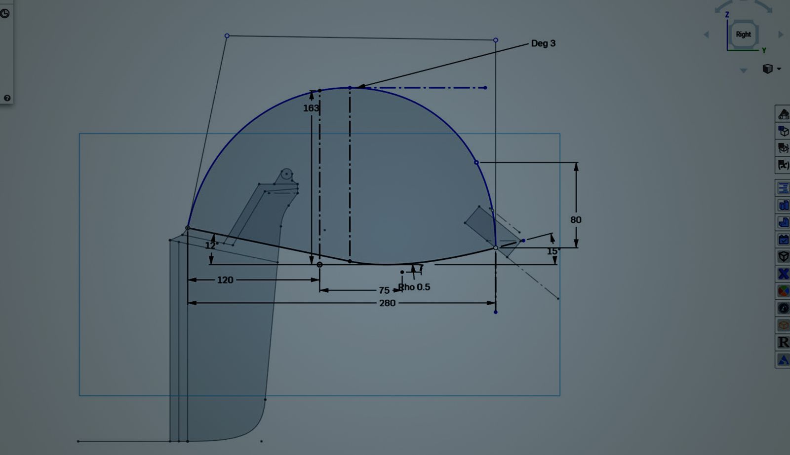
Just like any other sketch line, construction lines can be dimensioned to assist various applications. One of the most common use cases for dimensioning a construction line is to define the magnitudes or directions of spline handles or conics to better control the curvature they create.
Construction Lines as Part Studio Feature References
Once construction lines are created in sketches, they can be used as references for features. Construction lines are great axis references for revolve or mirror features. The same construction line can even be used multiple times across features to ensure concentricity between components.
In addition to using them as feature references, mate connectors can be attached to construction geometry in reference sketches to serve as skeleton references in assemblies further downstream.
Construction Lines in Assemblies
Many master sketches contain construction lines for positioning. This is handy when building a top-level assembly. With mate connectors attached to construction lines, they can become mating references for parts and assemblies to maintain the intended structure from sketch to assembly.
Construction Geometry in Drawings
Construction geometry is not only for parts and assemblies. Use lines and centerpoints as construction references on drawings. Centerlines can define lines of symmetry in a part and can even be dimensioned. For circular geometry, centerpoints can be added to denote center reference points for circles and arcs.
These are just a few examples of where construction lines add much-needed references to your Onshape designs. Try them out for yourself and check out the rest of Onshape’s recent technical blogs here.
Friends Don’t Let Friends Use Old CAD!
Know a colleague who could benefit from our cloud-native, fully-featured collaborative design platform?
Latest Content
- Blog
- Becoming an Expert
- Assemblies
Built to Scale: Why Large Assemblies Don’t Slow Down in Onshape
07.16.2026 learn more- Blog
- News from Onshape @ PTC
- Artificial Intelligence
Onshape Labs: AI in CAD Guided by Designers, Driven by Innovation
07.15.2026 learn more- Blog
- Evaluating Onshape
- Data Management
- Collaboration
- Artificial Intelligence
How the Most Underrated CAD Feature Improves Design Workflows
07.09.2026 learn more