
02:31
Datums and geometric tolerances are integral to communicating manufacturing variation in Onshape Drawings. Whether defining a functional reference or controlling tolerance zones, knowing how to efficiently place, move, and edit datum symbols ensures drawings stay accurate and professional.
In this Tech Tip, explore practical ways to work with datums in Onshape, including how to place them on geometry, reposition them for clarity, and associate them with dimensions and callouts to keep your drawings standards-compliant.
Placing and Moving Datum Symbol
In Onshape, datums serve as key reference points, lines, axes, or planes used in Geometric Dimensioning and Tolerancing (GD&T). They ensure features line up correctly and help verify that manufactured parts meet design requirements. To make this process smooth, Onshape provides flexible tools for placing and repositioning datum symbols so drawings remain both standards-compliant and easy to read.
When adding datums, each datum is assigned a sequential letter, but the label can be edited at any time. While the datum tool is active, multiple symbols can be placed in succession without reactivating the command, making it easy to set up several references at once.
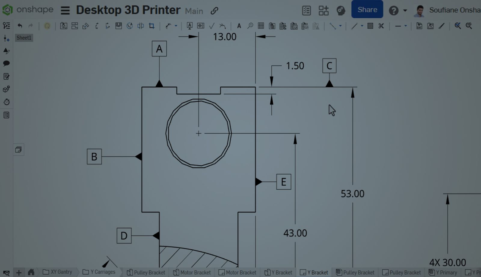
A datum can be placed on planar or circular faces, edges, or directly on dimension lines. Once inserted, it can be repositioned at any time by clicking and dragging its symbol.
Editing and Styling Datums
Onshape gives full control over the appearance of datum symbols, making it easy to tailor them to the drawing’s requirements. Double-click a symbol to edit its label. Use the Style panel on the right to adjust the font size, text height, color, or switch between open and filled triangle arrowheads.
Using Datums on Circular and Cylindrical Features
A datum in Onshape can also be placed on a diameter or radius leader to define an axis for a hole or a circular feature, connected to a hole callout, or attached to a feature control frame. For holes, slots, and cylinders, the datum usually represents the axis or middle plane rather than the surface, and attaching it to a diameter leader or directly to the feature ensures proper alignment.
A datum can also be snapped to leader lines or dimension extension lines. If moved beyond the dimension, the leader line automatically adjusts to extend further so it stays in place even if the dimension is deleted, since it references the geometry itself.
Note: Datums can also be grouped with callouts to improve organization and maintain clarity, ensuring annotations remain easy to follow without being overwhelming. This flexibility helps prevent misalignment, keeps drawings standards-compliant, and makes manufacturing intent clear.
By applying these tips, datums are efficiently placed, adjusted, and organized in Onshape Drawings, making annotations clearer and ensuring that designs meet manufacturing standards.
To learn more about Onshape drawings and GD&T workflows, visit the Onshape Learning Center or explore related Tech Tips on Drawings.
The Onshape Learning Center
Take self-paced courses, read articles, or sign up for an instructor-led training session.
Latest Content
- Blog
- Evaluating Onshape
- Electronics
- Integrations
- PCB Studio
How Onshape PCB Studio Pulls 3D Component Models Straight from Altium 365
05.21.2026 learn more- Blog
- Evaluating Onshape
- Collaboration
- Data Management
What’s the Difference Between File-Based and Cloud CAD?
05.20.2026 learn more- Blog
- Customers & Case Studies
- Arena PLM Connection
The Cloud-Native Workflow Behind Coco’s Next-Gen Delivery Robot
05.14.2026 learn more