
01:08
Sometimes, part geometry does not provide all the information required for an efficient toolpath.
This Tech Tip shows you how to create machining-specific geometry for use in CAM Studio.
You can use surfaces or curves as references for toolpaths.
It may come as a surprise, but toolpaths need not reference actual design geometry. Surfaces or curves created in a Part Studio can be used for toolpaths.
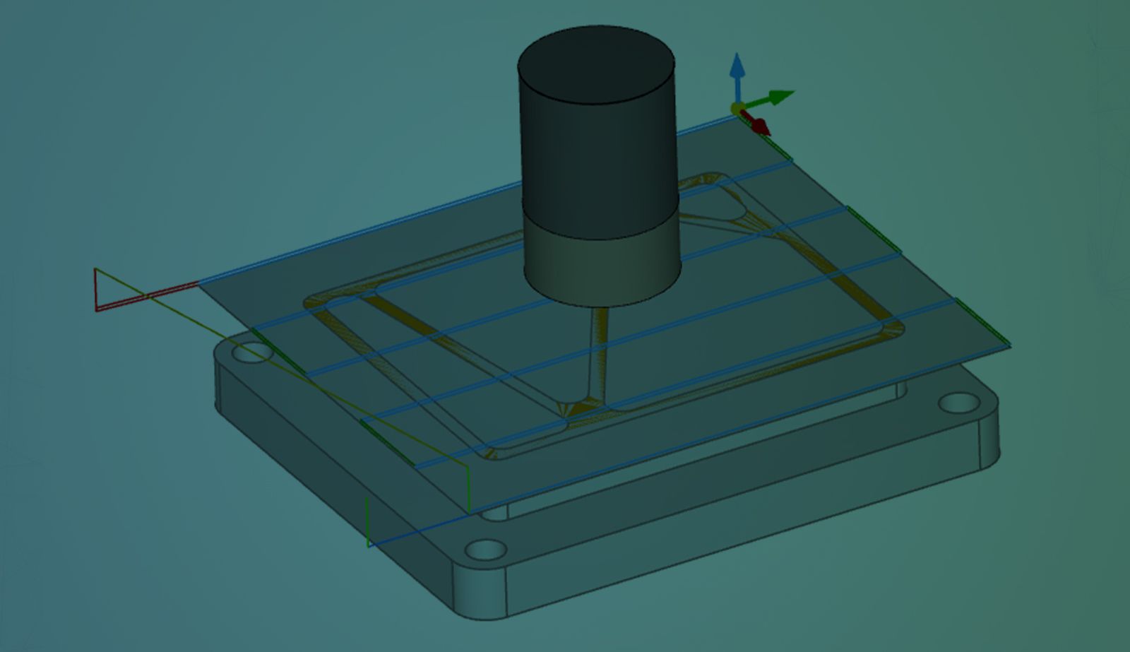
Consider the part in the image below. The stock is .25” thicker than the part, and .25” must be removed from the top with a facing operation. The top face of the part (orange face) is interrupted, and internal loops should be ignored for machining purposes. Creating a surface in the part studio solves this problem.
Create Machining-Specific Geometry in a Branch
A branch is a great place for machining-specific geometry. Programmers can operate in the branch without impacting design efforts. Changes from the Main workspace can be merged into the branch, and toolpaths can be updated.
The surface from the Part Studio is brought into CAM Studio by adding it as a component. The surface's display can be turned on or off, and it can be referenced for the facing toolpath.
This Tech Tip showed you how to create machining-specific geometry for efficient toolpaths.
Interested in learning more with Onshape Tech Tips? You can review the most recent technical blogs here.
The Onshape Learning Center
Take self-paced courses, read articles, or sign up for an instructor-led training session.
Latest Content
- Blog
- Evaluating Onshape
- Arena PLM Connection
The Cloud-Native CAD-PDM-PLM Workflow That Finds Problems Before They Cost You
06.11.2026 learn more- Blog
- News from Onshape @ PTC
- Artificial Intelligence
- Robotics
How Multi-Agent Orchestration Between Onshape and NVIDIA Improves CAD-to-Simulation Workflows
06.01.2026 learn more- Blog
- Evaluating Onshape
- Robotics
- Aviation, Aerospace & Defense
- Collaboration
- Integrations
- Arena PLM Connection
- Data Management
Why the Best Hardware Teams Have Started Talking Like Software Engineers
05.28.2026 learn more