
04:58
Summary
Onshape unifies top‑down design and semantic PMI to preserve design intent and manufacturing accuracy through every change.
If you are transitioning from traditional, legacy CAD tools, you are likely familiar with the headaches of the past: bottom-up design workflows that lead to broken assembly references, and disconnected 2D drawings that inevitably cause costly miscommunications on the manufacturing floor.
Onshape has completely redefined this workflow. By combining a unique approach to top-down modeling—using multi-part Part Studios and controlled in-context design—with the newly integrated Model-Based Definition (MBD), Onshape doesn’t just make modeling faster. It creates an unbreakable, machine-readable thread from your initial concept straight to the shop floor.
Let's explore how merging top-down design with semantic Product Manufacturing Information (PMI) is changing the game for hardware development.
A True Single Source of Truth for Design and Manufacturing
In traditional CAD, you design one part per file and then assemble them later. This bottom-up approach makes it incredibly difficult to manage relationships between components. Onshape flips this on its head with the multi-part Part Studio.
Onshape allows and encourages you to design multiple related parts together within a single workspace (a Part Studio). Instead of jumping between disconnected files, you create shared sketches and features that define and modify multiple components simultaneously.
Enter semantic PMI.
Geometry is only half the battle; parts also need manufacturing instructions. This is where MBD comes in.
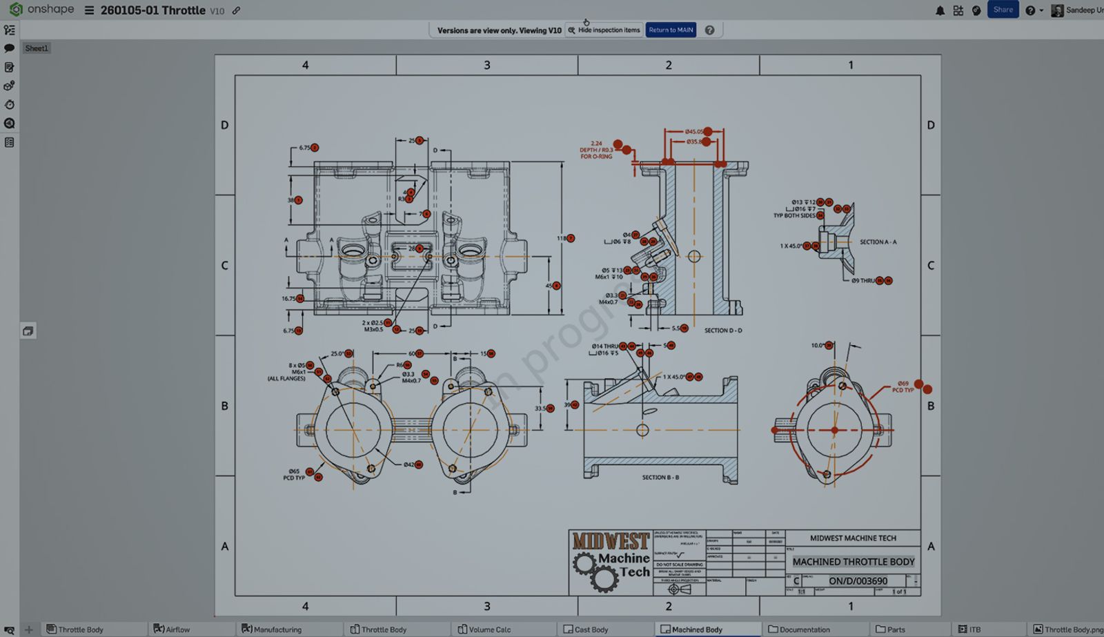
Unlike “dumb” text annotations typed onto a 2D PDF drawing, Onshape’s MBD has deep semantic relations to its geometry. This means that the PMI—like geometric dimensioning and tolerancing (GD&T), surface finishes, and datums—is mathematically and digitally attached directly to the CAD feature in the feature tree.
When you design top-down in a Part Studio, the shared geometry is your foundation. By applying semantic PMI to that shared geometry, your manufacturing data is embedded into the exact same environment as your design intent. There are no external drawing files to fall out of sync. For the first time, every engineer, manufacturer, supplier, and quality inspector can open the exact same live 3D model in a browser and see every tolerance exactly as the designer defined it.
The Cascading Stability Effect on Semantic PMI
The inherent stability of Onshape's top-down design methodology directly ensures the integrity and reliability of its semantic PMI. This creates a beneficial “cascading stability effect” that eliminates the typical fragility found in legacy CAD systems, which means:
Stable Geometry Foundation: By centralizing design in the multi-part Part Studio, all related components are defined by shared, stable sketches and features. This top-down definition minimizes the chance of individual component geometry becoming corrupt or losing its reference context when changes are made.
PMI Integrity is Inherited: Because semantic PMI is mathematically attached directly to the stable 3D faces and features of the model, the PMI inherits the stability of the underlying geometry. If the geometry reference remains intact (as is designed to happen in Onshape), the tolerance, finish, or datum callout remains correctly linked.
Controlled Update Prevents Breakage: When a change in an assembly could affect a reference part (and thus its attached PMI), Onshape only notifies the user. It does not automatically destroy the reference or break the PMI. The documentation (MBD/PMI) remains stable and valid until the designer consciously reviews the change and initiates the update.
Try top-down design now with PMI included with this public example:
Designing to Capture Intent
Onshape’s approach to product development represents a massive, necessary shift away from the restrictive and often cumbersome file-based part-and-assembly paradigms of legacy CAD systems. This new methodology is centered on holistic, intelligent design creation.
By leveraging powerful tools such as multi-part Part Studios, controlled in-context references, and fully integrated semantic Model-Based Definition (MBD), users are no longer simply creating isolated 3D shapes. Instead, they are building a complete, intelligent, and immediately manufacturing-ready digital definition of their product right from day one.
Central to this idea is the preservation and explicit capture of design intent. This is achieved through the unified history tree, a robust, chronological ledger that logs every single design change, feature modification, and sketch adjustment. This history ensures that the original design vision is always traceable and provides a fully non-destructive editing environment. Users can jump back to any point in the design process, make modifications, and watch the changes cascade forward reliably.
Furthermore, the foundational use of variables and feature-based modeling provides an unparalleled level of robust parametric control. This clarity makes it explicitly transparent how different elements of the design relate to and influence each other, eliminating guesswork and dramatically reducing the risk of errors during complex modifications.
To manage the complexity inherent in advanced product design, Onshape provides tools for organization and clarity. Within the Part Studio, users can maintain a clean, navigable design structure by organizing features within the Part Studio’s feature tree, leveraging folders and grouping to manage hundreds of features efficiently.
Beyond the Part Studio itself, the Document structure is equally powerful. Users utilize folders to group related Part Studios, Assemblies, Drawings, and imported data, ensuring that large, multi-part projects remain coherent and easy to navigate for every member of the design team. This structural integrity is crucial for collaborative environments, ensuring that any team member can quickly understand and contribute to the project’s architecture.
Watch the demo on top-down design:
The Onshape Discovery Program
Learn how qualified CAD professionals can get Onshape Professional for up to 6 months – at no cost!
Latest Content
- Blog
- Becoming an Expert
- Assemblies
Built to Scale: Why Large Assemblies Don’t Slow Down in Onshape
07.16.2026 learn more- Blog
- News from Onshape @ PTC
- Artificial Intelligence
Onshape Labs: AI in CAD Guided by Designers, Driven by Innovation
07.15.2026 learn more- Blog
- Evaluating Onshape
- Data Management
- Collaboration
- Artificial Intelligence
How the Most Underrated CAD Feature Improves Design Workflows
07.09.2026 learn more