
02:23
When documenting an assembly, we usually want to show internal components as well. It’s often important to capture them in the context of the overall assembly, rather than just on their own.
In Onshape drawings, you can easily create a broken-out section view. Depending on drawing standards, this may not be what you are looking for; a broken-out section is typically used to highlight local internal features, usually for manufacturing.
When your goal is to illustrate the internals with the goal of communication – typically for assembly instructions or other visual explanation of the assembly function – a cutaway view is really what you’re after.
In this Tech Tip, we’ll look at a simple way to create an assembly cutaway view leveraging Named views in your Onshape assembly.
Assembly Section View
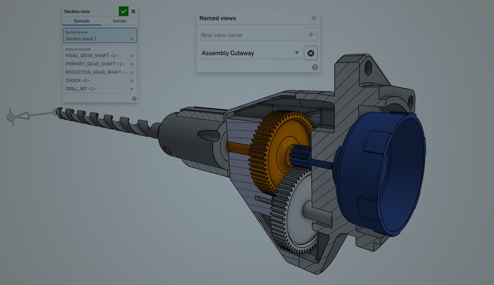
In your Onshape assembly, you can easily view your model as sectioned using the Section view tool, available from the context menu. We won’t go into the details of using this feature, but it was discussed in a previous Tech Tip.
Simply set up the section view exactly as you’ll want to see it cut away in the drawing.
Tip: Remember to use the Items to exclude selections. This allows you to control which parts are being cut away and which are not.
Capture a Named view
Named views are a powerful way to quickly capture an orientation of a model, making it easy to return back to a specific view at a later point. Once again, we won’t go through the step-by-step, since it also has been covered by a previous Tech Tip.
Named views not only capture the orientation and zoom/scale of your model, but also the status of other options, one of which is the Section view. You can use the View cube in the top-right corner to ensure you’re using a standard view (front, top, right, etc.) or, selecting a face, use the shortcut key “N” to view normal to that face. Make sure that your Section view remains turned on as you create the Named view.
Placing the Assembly Cutaway View in the Drawing
In the Onshape drawing, select Insert view. From the View orientation dropdown, you will find your Named view available. The created view will respect the section created in the assembly environment. Hatching will automatically be applied to any cut faces.
You may, of course, add any dimensions or annotations to the view as you require. Additionally, you can define a Detail view, Break, or Crop your assembly cutaway view.
A Clear and Simple Definition
Assembly cutaway views are a powerful illustrative technique that shows how components fit together inside an assembly.
Defining them using a Named view in the assembly allows for a clear and simple definition of your cutting planes in the 3D environment. Since you can have any number of Named views in an assembly, you can create any number of custom views you may need in your drawings to clearly convey your requirements.
Friends Don’t Let Friends Use Old CAD!
Know a colleague who could benefit from our cloud-native, fully-featured collaborative design platform?
Latest Content
- Blog
- Becoming an Expert
- Assemblies
Built to Scale: Why Large Assemblies Don’t Slow Down in Onshape
07.16.2026 learn more- Blog
- News from Onshape @ PTC
- Artificial Intelligence
Onshape Labs: AI in CAD Guided by Designers, Driven by Innovation
07.15.2026 learn more- Blog
- Evaluating Onshape
- Data Management
- Collaboration
- Artificial Intelligence
How the Most Underrated CAD Feature Improves Design Workflows
07.09.2026 learn more