
02:23
With Onshape’s Move Face feature, you can offset, translate, or rotate one or more selected faces.
This Direct Editing tool is especially convenient if you don't have the parametric history of a part, which is often the case with any imported geometry. It could also be just as powerful for quick edits to your native designs, making it a versatile tool to have in your CAD arsenal.
Move Face: Offset
Offset is most often used with non-planar faces to increase or decrease a radius, such as a cylinder. Once you select Move Face from the Onshape toolbar, Offset will be the default choice in the type dropdown.
- Select the faces to move
- Choose your end condition
- Blind: A distance can be entered or you can simply drag the onscreen arrow, click the same arrow or the reverse direction button in the feature window to reverse the direction
- Up to Entity: Select an entity to offset up to, such as face, surface, edge, or vertex
Move Face: Translate
This is useful for moving a face or collection of faces, such as an entire protrusion or boss, in a referenced direction. Select the Move Face feature from the Onshape tool bar and then select Translate from the type dropdown.
- Select the faces to move
- In the Direction field, select a direction reference, such as a Mate connector (implicit or explicit) or axis (to define the direction vector parallel to the selected Mate connector), an edge (to define the direction vector parallel to the selected edge), or a face (to define the direction vector normal to the selected face).
- Choose your end condition
- Blind: A distance can be entered or you can simply drag the onscreen arrow, click the same arrow or the reverse direction button in the feature window to reverse the direction
- Up to Entity: Select vertex or parallel face to translate up to. Optionally, use Offset distance to create an offset between faces.
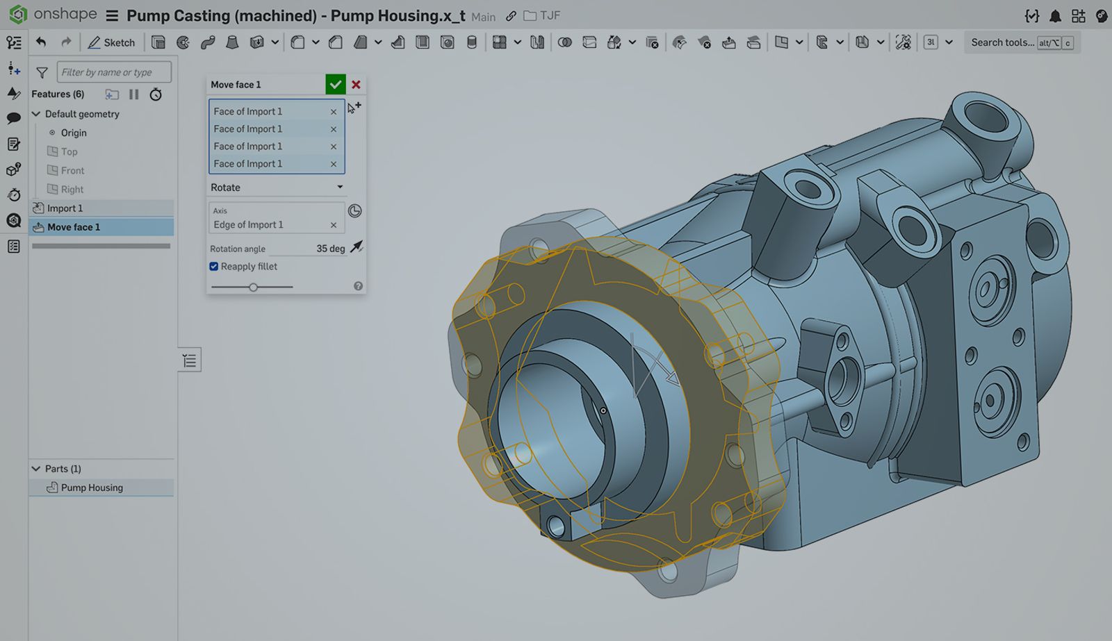
Move Face: Rotate
This is useful for rotating a face or collection of faces a specified number of degrees around a selected reference axis. Select the Move Face feature from the Onshape tool bar and then select Rotate from the type dropdown.
- Select the faces to move
- In the Axis field, select a center of rotation reference, such as a Mate connector (implicit or explicit), edge, or cylindrical face
- Enter your precise angle of rotation, or drag the onscreen arrow, click the same arrow or the reverse direction button in the feature window to reverse the direction.
Another option that you’ll see in the Move Face feature window with all of these types is the Reapply Fillet checkbox. Any of these movements can affect filleted faces attached to the selected faces being moved. Use this option to reapply those fillets after the movement, thus maintaining their original size.
As a Tip within the Tip: Use the Create Selection tool to speed up and assist the selection of multiple faces when using the Move Face feature.
Friends Don’t Let Friends Use Old CAD!
Know a colleague who could benefit from our cloud-native, fully-featured collaborative design platform?
Latest Content
- Blog
- Evaluating Onshape
- Arena PLM Connection
The Cloud-Native CAD-PDM-PLM Workflow That Finds Problems Before They Cost You
06.11.2026 learn more- Blog
- News from Onshape @ PTC
- Artificial Intelligence
- Robotics
How Multi-Agent Orchestration Between Onshape and NVIDIA Improves CAD-to-Simulation Workflows
06.01.2026 learn more- Blog
- Evaluating Onshape
- Robotics
- Aviation, Aerospace & Defense
- Collaboration
- Integrations
- Arena PLM Connection
- Data Management
Why the Best Hardware Teams Have Started Talking Like Software Engineers
05.28.2026 learn more