
02:35
TL;DR: When physical thread geometry is required in Onshape, custom features like Thread Creator offer the fastest, most robust solution. For non‑standard threads, manual helix-and-sweep modeling still matters. The key is knowing when to model threads and when to leave them cosmetic.
While the debate between cosmetic threads and modeling threads is well-documented, certain applications, such as 3D-printed prototypes or custom threads, demand true physical geometry.
In this Tech Tip, we’ll cover both manual and custom feature-based thread creation techniques…the choice is yours.
Use Custom Features for Standard Threads
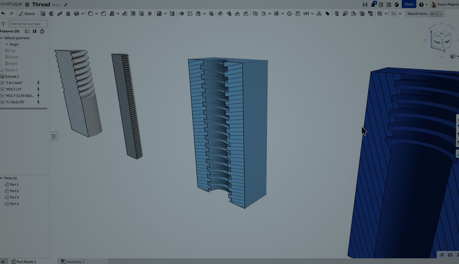
The most efficient way to handle physical threads in Onshape is via FeatureScript and custom features. Rather than manually rebuilding the same geometry for every bolt, the community has developed high-performance custom features that automate the process.
The Thread Creator custom feature is my go-to because it condenses a multi-step geometric operation into a single dialogue box.
- Standardization: Instantly select ISO or ANSI profiles without looking up pitch tables.
- Performance: These scripts are optimized to generate geometry that is “lighter” on your assembly than manual sweeps.
- Robustness: If you change the diameter of your host cylinder, a well-built custom feature will update the thread parameters automatically, preventing broken features.
Using the Thread Creator Custom Feature
Simply add “Thread Creator” to your toolbar via the public document search, select your cylindrical face, and define your parameters.
Manually Build Non-Standard Threads
While automation is the daily driver, every engineer should master the manual method for non-standard geometry or custom hardware.
If you need to build a thread from scratch, follow this general workflow:
- The Base: Create your cylinder to the correct major diameter.
- The Path (Helix): Use the Helix tool. In professional applications, it is best to define this by "Pitch" and "Height" to ensure the thread count remains accurate during length adjustments.
- The Profile: Sketch the thread cross-section on a plane perpendicular to the start of the helix. Ensure you include a "pierce" constraint between the profile’s vertex and the helix path to avoid sweep errors.
- The Sweep: Execute a Sweep command, using the sketch as your profile and the helix as your path. Set the operation to "Remove" to cut the threads into the material.
When to Not Model Threads: Modeling vs. Annotation
A professional design approach requires knowing when not to model threads.
- Physical Modeling: Use this for 3D printing/manufacturing, or for high-end renders where the thread’s physical presence is required for functionality or aesthetics.
- Cosmetic Threads: For standard assemblies and 2D drawings, lean on Onshape’s native Thread tool for annotations. This keeps your Part Studio fast and your assembly performance high.
At the end of the day, choose what’s right for you and your needs.
More Tech Tips on threads:
Friends Don’t Let Friends Use Old CAD!
Know a colleague who could benefit from our cloud-native, fully-featured collaborative design platform?
Latest Content
- Blog
- Evaluating Onshape
- Arena PLM Connection
The Cloud-Native CAD-PDM-PLM Workflow That Finds Problems Before They Cost You
06.11.2026 learn more- Blog
- News from Onshape @ PTC
- Artificial Intelligence
- Robotics
How Multi-Agent Orchestration Between Onshape and NVIDIA Improves CAD-to-Simulation Workflows
06.01.2026 learn more- Blog
- Evaluating Onshape
- Robotics
- Aviation, Aerospace & Defense
- Collaboration
- Integrations
- Arena PLM Connection
- Data Management
Why the Best Hardware Teams Have Started Talking Like Software Engineers
05.28.2026 learn more