
02:44
When you’re designing in Onshape, one of the things that can take your skills to the next level is using mate connectors in more ways than just creating mates.
Mate connectors can be used in a variety of ways, from defining sketch planes to acting as end conditions for features like extrudes. However, they’re not always placed right where you want them by default.
In this Tech Tip, we’ll take a look at the different ways you can redefine implicit mate connectors in Onshape.
Selecting a Mate Connector for a Feature
In a Part Studio, whenever a mate connector is able to be selected for a feature, you can either select a pre-defined mate connector or create one on-the-fly using the mate connector icon in the feature dialog.
For these examples, all mate connectors here will be created on-the-fly, but if you need to use a mate connector for multiple different operations, you can create a Mate Connector Feature in the Feature List.
The on-the-fly method is useful when you need a quick reference for a feature without creating extra geometry or planes.
Accessing the Mate Connector Definition Dialog
After selecting your mate connector, you will see a smaller icon pop up in the entity selection box. This icon will allow you to edit the definition of the mate connector, with the options to realign, move, or flip/rotate the axes. There is also an option to change the mate connector definition from “On Entity” to “Between Entities.”
Editing the Axis of Mate Connectors
There are two ways to edit the axes of mate connectors in this dialog box. The first option is to realign the mate connector with existing geometry. First, click the checkbox next to “Realign.” Then, select a primary axis entity. This can be a sketched line, an edge, a plane, or a planar face. This aligns the Z axis of the mate connector to the selected geometry.
The second option is to flip the primary axis of the mate connector, which will change the positive and negative orientations of the Z axis, or rotate the secondary axes, which rotates the connector 90° about the Z axis.
These options are especially useful when your feature needs to follow a specific direction, like aligning an extrude or hole with an angled edge or face.
Adjusting the Position of Mate Connectors
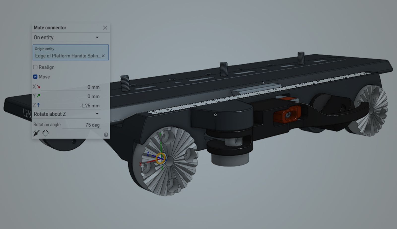
To edit position and orientation, use the Move checkbox. This will open a dialog containing movement options for the X, Y, and Z directions, as well as an option to specify a number of degrees to rotate around any of those axes. These options are useful for dialing in exact offsets, like placing a hole a fixed distance off a face or shifting a split location.
Switching the Definition Type
You can also use the dropdown at the top of the dialog to change your mate connector definition type from “On Entity” to “Between Entities.” This is useful when you need a mate connector at a midplane between two entities. In the example above, the mate connector is used as the plane to place a set screw hole, and is defined halfway between the top of the boss and the face of the spur gear.
Once you get comfortable editing mate connectors like this, you can avoid creating extra reference geometry and keep your Part Studio cleaner.
For more information on ways to use mate connectors, check out our Resource Center or the Onshape Learning Center.
The Onshape Learning Center
Take self-paced courses, read articles, or sign up for an instructor-led training session.
Latest Content
- Blog
- Evaluating Onshape
- Arena PLM Connection
The Cloud-Native CAD-PDM-PLM Workflow That Finds Problems Before They Cost You
06.11.2026 learn more- Blog
- News from Onshape @ PTC
- Artificial Intelligence
- Robotics
How Multi-Agent Orchestration Between Onshape and NVIDIA Improves CAD-to-Simulation Workflows
06.01.2026 learn more- Blog
- Evaluating Onshape
- Robotics
- Aviation, Aerospace & Defense
- Collaboration
- Integrations
- Arena PLM Connection
- Data Management
Why the Best Hardware Teams Have Started Talking Like Software Engineers
05.28.2026 learn more