
1:60
We have an awesome update for you! This update includes major new surfacing tools, a new drawing view tool, improvements to Loft, Hole feature, and more. Let's check it out.
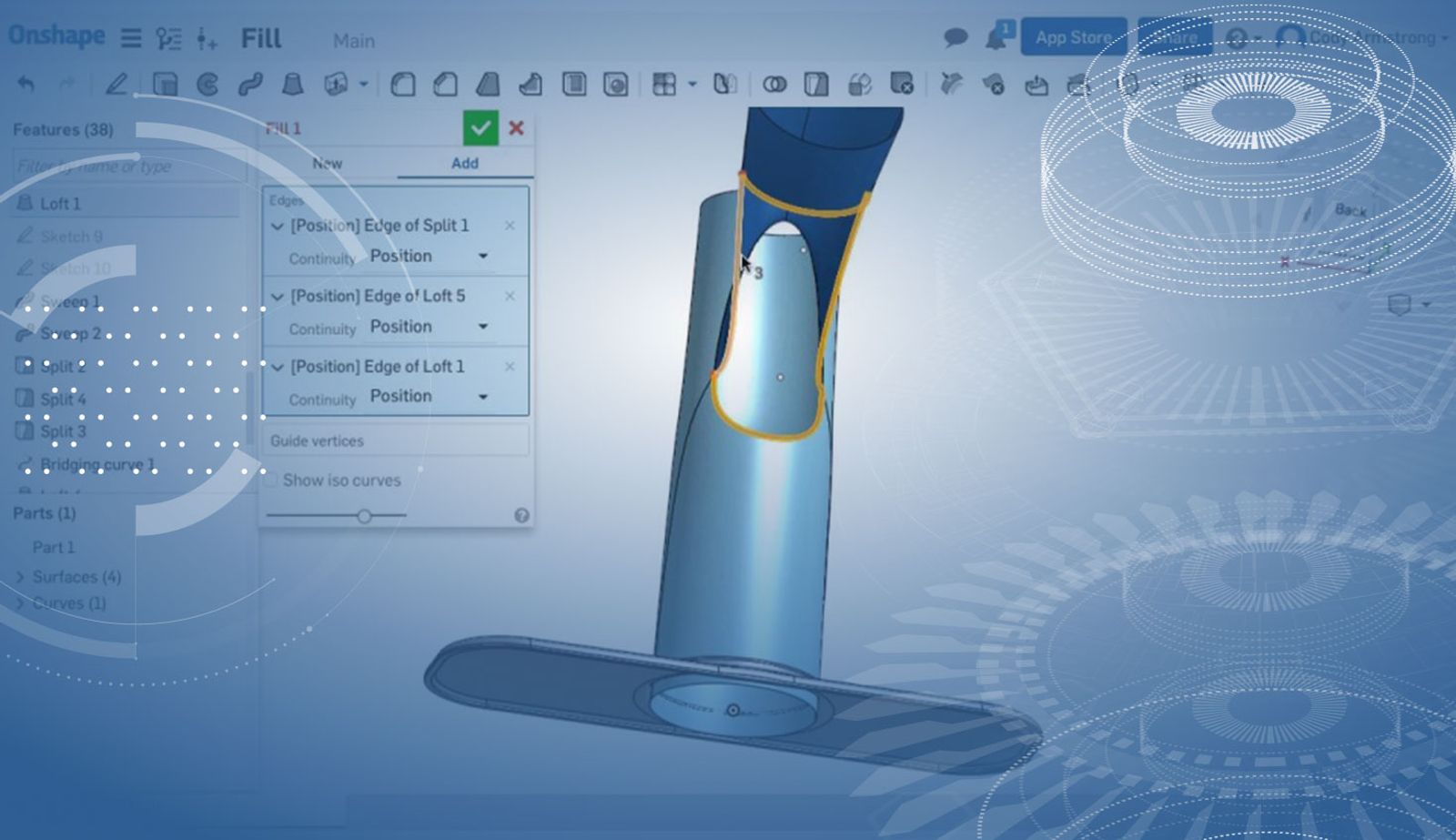
FILL
You can now create a surface defined by a boundary of edges or curves.
Enclose
Create a solid part from an enclosed selection of surfaces or planes.
GUIDES AND END CONDITIONS IN LOFT
You can now use a combination of guides and end conditions in the Loft command. In the past, you had to choose one or the other.
SAVE SECTION VIEWS AS NAMED VIEWS
With this update comes the ability to save section views as named views in your model. This can be useful if you find yourself consistently creating the same section view. Simply create a named view while in your section view and it will be easy to return to that view at a later point.
HOLE FEATURE IMPROVEMENTS
There were many improvements to the Hole feature with this update. Including new standard hole sizes, and the ability to create holes in sheet metal parts.
SECTION VIEW IMPROVEMENTS
You'll find a new "Angular" section view type in Onshape Drawings. This option allows you to create section views at an angle. Also added with this update is the ability to change a view's label.
COPY/PASTE CONTEXT MENU IN ONSHAPE DRAWINGS
You can now right-click "Copy" and right-click "Paste" entities in Onshape Drawings. In this past this was limited to keyboard shortcuts.
WELD SYMBOL IMPROVEMENTS
A few important improvements to Weld symbols were added with this release. This includes live updates to the Weld symbol preview, as well as support for staggered welds.
ORDERED ARRAY OF FEATURESCRIPT PARAMETERS
The foundation has been laid to allow you to make per selection changes to parameters in Onshape while creating a feature. This means you can have different settings for each selection within a dialog. Currently, you can only see this in the Fill command (where you can make "per edge" continuity choices), but we are working on more features with this capability. Below is an example of the custom "Port Feature" that has been modified to allow the user to change port size for each selection.
PERFORMANCE IMPROVEMENTS
Performance has been improved in several areas including assemblies, drawings, holes and more.
Latest Content
- Blog
- Becoming an Expert
- Assemblies
Built to Scale: Why Large Assemblies Don’t Slow Down in Onshape
07.16.2026 learn more- Blog
- News from Onshape @ PTC
- Artificial Intelligence
Onshape Labs: AI in CAD Guided by Designers, Driven by Innovation
07.15.2026 learn more- Blog
- Evaluating Onshape
- Data Management
- Collaboration
- Artificial Intelligence
How the Most Underrated CAD Feature Improves Design Workflows
07.09.2026 learn more