
03:42
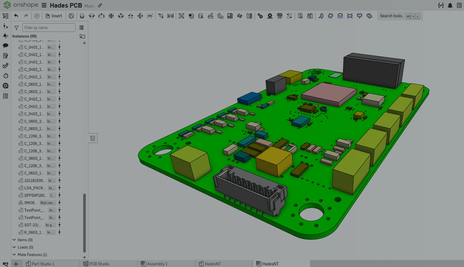
A significant factor of assembly performance is the number of parts within referenced Part Studios.
Onshape recommends keeping each Part Studio to between one and 10 unique parts to ensure optimal performance. Importing PCB STEP files frequently exceeds this threshold by generating a large number of (and many duplicate) parts.
A common misconception is that creating a composite part after importing a PCB into a Part Studio reduces complexity. While composite parts are useful for grouping geometry, they do not decrease the overall complexity of the Part Studio. All geometry remains present, so performance is affected similarly to that of any large multipart Part Studio.
Improper management of PCB data can result in performance bottlenecks in Onshape, affecting graphics rendering, selection, assembly mating, regeneration times, and downstream workflows. Additionally, PCB components may include unnecessary geometric details for mechanical design.
Using PCB Studio to import IDF files and control the level of PCB detail in Onshape assemblies is a more effective strategy. PCB Studio helps manage imported geometry, prevent the creation of large multipart Part Studios, reduce unnecessary detail, and enhance performance.
Managing PCB data and referencing versioned, linked documents maintains design speed, stability, and usability, while preserving design intent.
Explanation of IDF Files
IDF (Intermediate Data Format) is a neutral ECAD-to-MCAD format for exporting PCB board and component geometry for mechanical design workflows. It provides accurate PCB representations without transferring complete electrical schematics. IDF exports may be a single file or, more commonly, two files: An EMN file with board geometry and an EMP file with component data.
5 Steps for Using PCB Studio
PCB Studio is the best way to efficiently manage PCB data in Onshape. While there are many options, the basic process is straightforward.
Note: Before using PCB Studio, an Onshape admin must configure PCB Studio settings for the company.
1. Create a PCB Studio
In an Onshape document, click Insert new tab and select Create PCB Studio. This process adds a tab that enables interaction with the ECAD data.
2. Import the ECAD File
In the PCB Studio tab, click Import ECAD files and select a supported file type. This action creates a lightweight representation of a PCB assembly.
3. Configure the Component Mappings
By default, PCB Studio uses ECAD data to automatically generate simplified component shapes. You can also use a custom part for detailed 3D models or omit the component from the Onshape assembly entirely.
To modify a component's representation, open the Properties panel on the right and select a component in the graphics area. Choose the Custom part option and click Select custom part. In the dialog, select an Onshape document containing the desired part to replace the selected component on the board.
Alternatively, select the None option to remove the component from the assembly. This eliminates details not relevant to mechanical design and enhances performance by reducing the part count.
4. Translate the ECAD Data
To convert ECAD data into 3D CAD geometry, select Sync to Onshape. In the dialog, select Create new assembly and specify the features to include. This process generates a new Onshape document for each ECAD component and assembles the PCB within the active document.
5. Finalize the Assembly
The resulting assembly references a Part Studio containing the board geometry and versioned documents for each component. Referencing specific versions ensures optimal performance and accurate assembly instancing.
By default, the assembly does not include mates and remains unconstrained. To fully constrain it, select the board, choose Fix, then select Group and include the entire assembly. The assembly is now fully defined and ready for downstream workflows.
Pro tip: Open the assembly properties and set the Subassembly BOM behavior to control how the assembly appears on next-level Bills of Material.
Better ECAD-to-MCAD Workflows
PCB Studio is the recommended method for ECAD-to-MCAD translations to achieve optimal assembly performance.
In addition to the process described in this Tech Tip, PCB Studio enables bidirectional workflows with ECAD software, which are particularly advantageous for organizations utilizing the Altium Connector.
For more information, check out PCB Studio Fundamentals in the Learning Center.
The Onshape Learning Center
Take self-paced courses, read articles, or sign up for an instructor-led training session.
Latest Content
- Blog
- Evaluating Onshape
- Electronics
- Integrations
- PCB Studio
How Onshape PCB Studio Pulls 3D Component Models Straight from Altium 365
05.21.2026 learn more- Blog
- Evaluating Onshape
- Collaboration
- Data Management
What’s the Difference Between File-Based and Cloud CAD?
05.20.2026 learn more- Blog
- Customers & Case Studies
- Arena PLM Connection
The Cloud-Native Workflow Behind Coco’s Next-Gen Delivery Robot
05.14.2026 learn more