
02:38
Whether you’re working with legacy CAD data, 3D scans, or reverse engineering workflows, the ability to work with mesh and solid geometry is no longer a luxury; it’s a necessity.
That’s where mixed modeling in Onshape shines.
What Is Mixed Modeling?
Mixed modeling in Onshape allows designers to combine exact boundary representation (BREP) geometry – such as parametric solids and surfaces you typically make in Onshape – with inexact mesh data – like STL or OBJ files – within the same design environment. This means you can import a 3D scan of a part and build new features directly on top of it, using standard modeling tools like Boolean operations, splits, hole creation, and many more.
Unlike traditional CAD platforms, which sometimes treat mesh as graphic-only, uneditable (and unusable) blobs, Onshape treats mesh parts as first-class citizens. You can use them in assemblies, drawings, and simulations just like any other part.
TECH TIP: All the Ways to Use Meshes in Onshape
Why Mixed Modeling Matters for Modern Design Teams
Mixed modeling is especially powerful for teams working with:
- 3D scans of components, which are becoming more and more prevalent with technology improvements and decreasing costs. Often used for reverse engineering and aftermarket customization.
- Additive manufacturing workflows typically use mesh data, especially helpful when using lattices and other advanced design methods.
- AR/VR hardware, where mesh data can be generated.
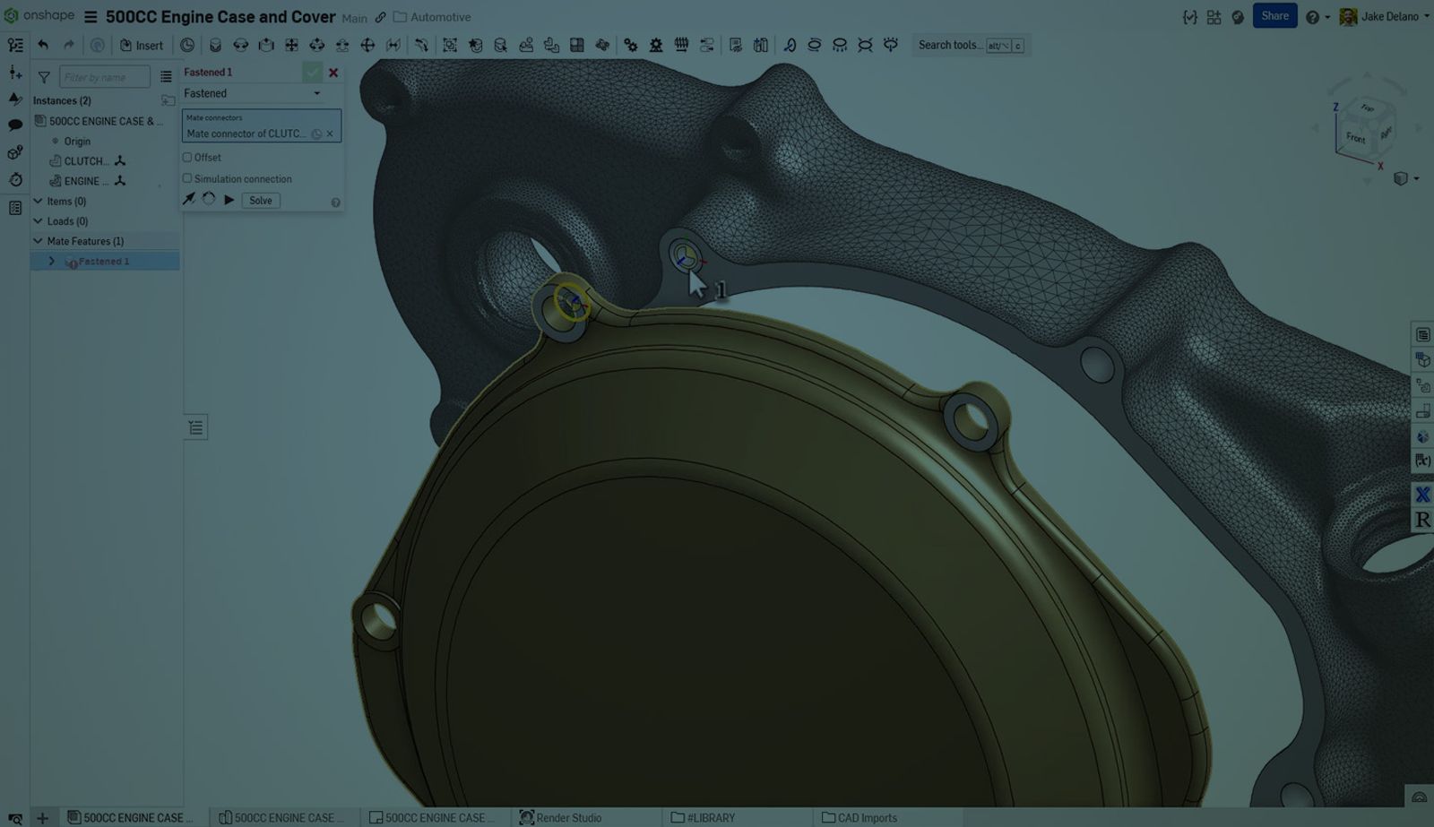
An example that really drives home the value of this is in aftermarket customization. How many companies out there thrive on aftermarket improvements for automobiles, motorcycles, bikes, and more? Want BREPs from those manufacturers? Best of luck to you! You’re best off taking a quick scan, measuring key connections, modeling, and prototyping, as shown in the following demo:
Fast Assembly and Rapid Simulations with Mixed Models
Once mixed models are inserted into an assembly, Onshape automatically generates mate connectors on solid faces, even those derived from mesh. This allows for precise alignment and fastener placement using Onshape’s standard content library.
And it doesn’t stop there. Onshape’s cloud-native simulation tools can run directly on mixed models, enabling real-time analysis without the need for geometry conversion or cleanup.
Drawings and Exporting Made Easy
Mixed models can be used in drawings with section views, detail views, and annotations. While mesh view quality depends on resolution, Onshape allows you to adjust render settings for best results. Exporting to formats like Parasolid or Rhino preserves both mesh and solid geometry, while STL and STEP convert the model to mesh.
TECH TIP: How to Import and Edit 3D CAD Geometry in Onshape
The Onshape Advantage
Mixed modeling is more than a feature – it’s a philosophy. It reflects Onshape’s commitment to collaborative workflows and design freedom. Whether you’re a startup scanning parts in a garage or a global manufacturer integrating mesh into BOM workflows, Onshape empowers you to design without constraints.
Ready to see mixed modeling in action? Watch this demo and explore how Onshape can transform your workflow.
The Onshape Discovery Program
Learn how qualified CAD professionals can get Onshape Professional for up to 6 months – at no cost!
Latest Content
- Blog
- Becoming an Expert
- Assemblies
Built to Scale: Why Large Assemblies Don’t Slow Down in Onshape
07.16.2026 learn more- Blog
- News from Onshape @ PTC
- Artificial Intelligence
Onshape Labs: AI in CAD Guided by Designers, Driven by Innovation
07.15.2026 learn more- Blog
- Evaluating Onshape
- Data Management
- Collaboration
- Artificial Intelligence
How the Most Underrated CAD Feature Improves Design Workflows
07.09.2026 learn more